This is part of a series of posts covering the development of a self-balancing robot:
The mathematical model of an inverter pendulum previously developed for the self-balancing robot, needs three parameters to accurately represent reality. These are
- Weight of the cart
- Weight of pendulum
- And the centre of gravity (COG) of the pendulum
The first two variables are easily obtained with a scale while the latter requires some arithmetic and will be the focus of this post.
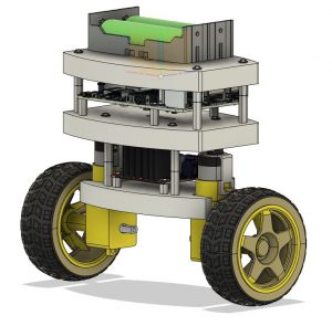
For the self-balancing robot, we can consider the hinge of the pendulum the wheel axes. This makes the wheels the cart and everything else the pendulum.
What is the centre of gravity?
The centre of gravity is the average location of the weight of an object [1]. The complete motion of an object can be described, in terms of translation, by using the centre of gravity.
Calculating the centre of gravity for a system
The centre of gravity of the robot can be calculated by taking the centre of gravity of the individual components and doing vector addition of the weighted position vectors [2]. What does this mean? For each of the axis, x, y and z, the centre of gravity are found with
![]()
![]()
![]()
where ![]() ,
, ![]() and
and ![]() is the weight of components 1, 2 and 3 making up the system and
is the weight of components 1, 2 and 3 making up the system and ![]() ,
, ![]() and
and ![]() is the coordinates of the centre of gravity for the first component,
is the coordinates of the centre of gravity for the first component, ![]() ,
, ![]() and
and ![]() for the second and
for the second and ![]() ,
, ![]() and
and ![]() for the third.
for the third.
Can this be applied to the self-balancing robot?
Yes, of course. As long as you know the COG and weight of every single component. The robot however contains a multitude of components, many of which the centre of gravity is unknown.
A package such as Fusion 360 will be able to calculate the COG if all of the individual components are accurately modelled. An investigation of the model shows this not to be the case. Downloaded components, such as the wheels, geared motor, H-bridge and Raspberry Pi do not have the correct material properties and the calculated weight do not match the real-world equivalent.
Another method of determining the centre of gravity is required.
Determining centre of gravity through measurement
The centre of gravity of a motorcar is obtained through measurement [4] and the same techniques will now be applied to the robot. For the robot, we assume each layer has been built symmetrical in both x-and y-directions. Furthermore, COG in the x-and y-directions are not important. They are not used in our mathematical model, in the y-direction we have the two wheel that keep it stable and if our x-COG is slightly off, we can compensate by moving our target control angle away from 0° in our control system. Therefor, we only need to determine the COG in the z-direction, the height of the centre of gravity.
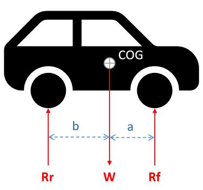
For motor vehicles the COG is determined by weighing the weight of the vehicle at each wheel and measuring the wheelbase.
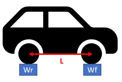 With these measurements we have the cars total weight W which we can model as a point mass at the centre of gravity.
![]()
As the car is not tipping over, we know the COG is somewhere between the front and rear axles. Furthermore, as the car is not moving, from Newton’s law we know the scales are applying a force equal to ![]() and
and ![]() in the opposite direction. Let’s call this force
in the opposite direction. Let’s call this force ![]() and
and ![]() .
.
With this information the longitudinal COG of the car can be determined. This is done by considering the moment about the rear wheel. As the car is not rotating around this point, the moments resulting from weight W at the COG and the force Rf at the front wheels, is cancelling each other. Mathematically this is written as:
![]()
From here we can make b the subject and thus determine the centre of gravity in the longitudinal direction.
![]()
Applying to the equation to the robot
As we consider the wheels not part of the robot, we remove them and weigh the pendulum part on its own.
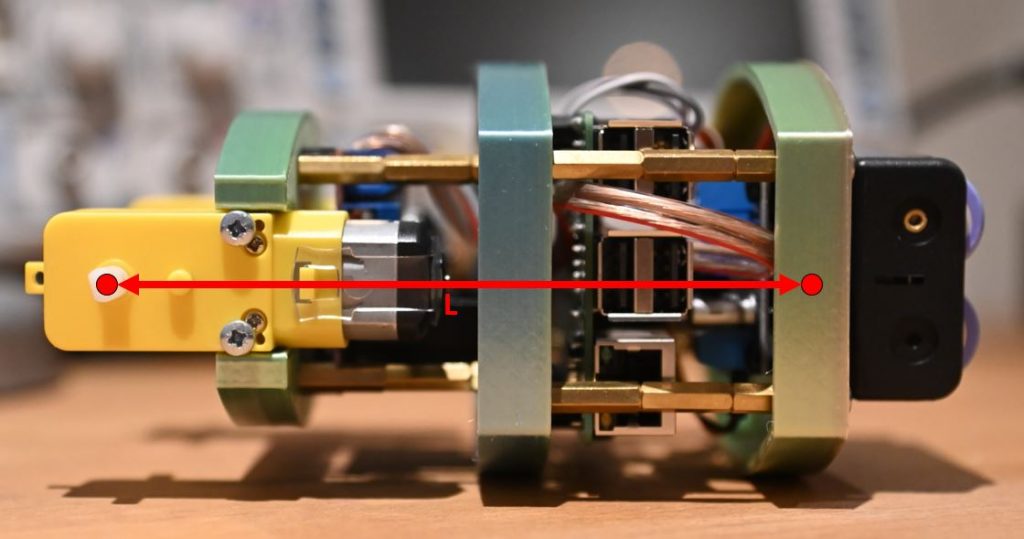
We now need to choose the two points at the bottom and top of the robot to weigh separately. For simplicity, the rotation axis of the motors are selected as one, while the other is chosen as close to the top as convenient. The distance between the two points are measured to determine the distance ![]() .
.
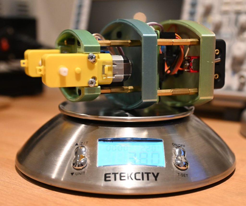
Next, keeping the robot level, the weight at the two points are measured. The two measurements should add up to match ![]() .
.
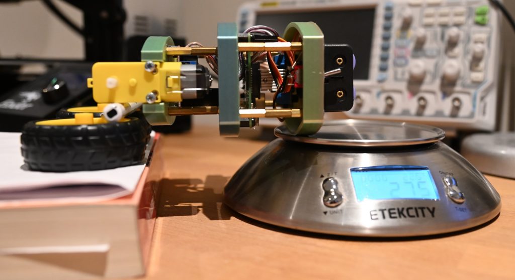
 Bottom weight
 ![]() . The scale was zeroed with the pen.
. The scale was zeroed with the pen.
Adding ![]() and
and ![]() we get 381g. Close enough for the accuracy we are working with.
we get 381g. Close enough for the accuracy we are working with.
 We have defined the top of the robot to match the front of the car and the bottom as the rear.
Now we can just enter the measurements into the equation to determine the height, ![]() , of the centre of gravity above the rotation axis of the robot
, of the centre of gravity above the rotation axis of the robot
![]()
![]()
![]()
Conclusion
The height of the centre of gravity has been calculated and we now have all the parameters required to accurately model the robot we have built.
Next, some coding is required to get the basic angle and position measurements from the robot. This will be used to validate our model and start with the control algorithm development.
Sources
[1] https://www.grc.nasa.gov/www/k-12/airplane/cg.html
[2] https://www.khanacademy.org/science/physics/linear-momentum/center-of-mass/a/what-is-center-of-mass
[3] http://www.thecartech.com/subjects/auto_eng/Center_of_Gravity.htm

