This is part of a series of posts covering the development of a self-balancing robot:
- Modelling an inverted pendulum
- This post
- Dertermining the centre of gravity for a self-balancing robot
Previously we investigated how to model an inverted pendulum. It is now time to go ahead and build the actual robot. This robot will use geared motors, a Raspberry Pi and a yet undetermined control strategy. Be on the look-out for a future post covering a different self-balancing robot running ROS and using stepper motors.
Parts list
The parts list of this build is below with links to UK sites (for transparency, some of these are affiliated links used to fund the site).
- Raspberry Pi 3b or 4 – Amazon UK Raspberry Pi 3b, Amazon UK Raspberry Pi 4b, The Pi Hut Raspberry Pi 4b
- L298N H-Bridge – eBay
- MPU6050 IMU – eBay
- LM317 DC-DC step-down converter – eBay
- TT hobby wheel and geared motors – eBay
- M3 bolts and nuts – local hardware store
- M3 brass hex standoff spacer – eBay
- M3 Nylon hex standoff spacer – eBay
- 18650 batteries – Amazon UK
- 18650 battery holder – eBay
- Toggle switch – eBay
- Amolen silk PLA 3D printing filament – Amazon
Design
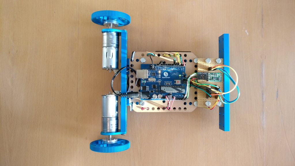
This being my third attempt, I had a good idea of what the robot would look like. Previous robots included one made from Makeblock aluminium beams and another using FR-4 board and stand-offs. Both used an Arduino Uno for control. Now, with my own 3D printer and the knowledge of the previous projects, I started my design in Autodesk Fusion 360. For control, I decided to move to a Pi instead. I experienced no problems with the Arduinos before, but wanted to try something new.

Fusion 360 design
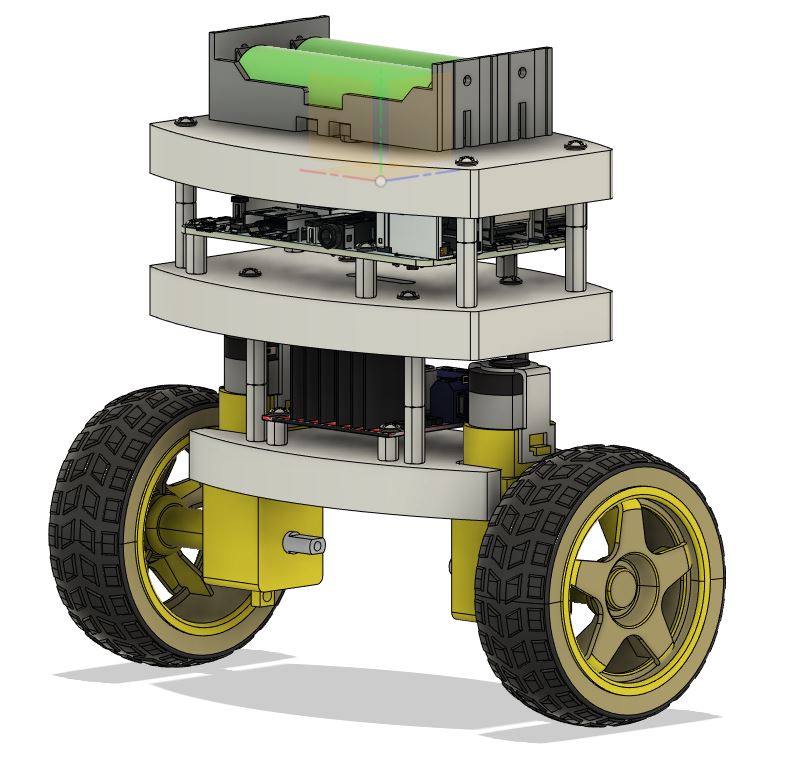
From previous experience, and the general design of these sort of robots on the internet, it was decided that the robot will consist of three layers
- Layer 1 – Geared motors and H-bridge board
- Layer 2 – Raspberry Pi
- Layer 3 – IMU and DC-DC converter mounted underneath layer and 18650 battery holder on top
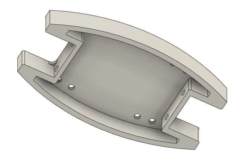
I really liked the shape of the FR-4 board used in the previous robot project and started with this shape in Fusion 360. The first step was to open the design file (received from the friend who previously cut the FR-4 for me) and add a lip around the lower edge of the shape to improve strength of the 3D-printed shape.
The first layer has exactly the same size as the FR-4 board, but layers 2 and 3 were enlarged to overhang the geared motors and provide enough space for the Raspberry Pi. For each layer mounting holes were positioned to align with the parts. An incredible useful resource during this phase of the design was GrabCAD. 3D models for the geared motors, wheels, L289n H-bridge, Raspberry Pi, battery holder and batteries could be downloaded and used to perfectly position each of the components. Using these models the full robot are modelled in Fusion 360.
Apart from being able to see exactly what the finished robot would look like, an additional motivation for using Fusion 360 was to determine the center of gravity (COG) of the robot. The center of gravity is an important property of the robot and is required for the mathematical modelling of it’s behaviour and design of control algorithms. This goal was abandoned as, although the mass density of the self-designed parts could be updated to match their real world counterparts, the GrabCAD downloaded models were too cumbersome to update. Calculation of the COG and will be revisited in a later post.
Build
With all the parts ordered and the layers 3D-printed the next step is assembly.
Power
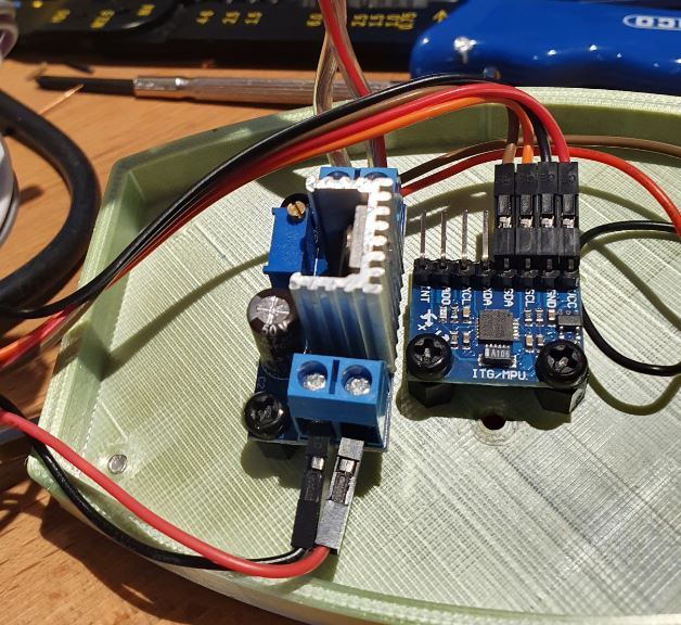
In the initial design in Fusion 360 the step down coverter was forgotten. This is essential to provide a regualted 5V to the Raspberry Pi. Space was found next to the IMU on the underside of the top layer of the robot. To provide enough room between the LM317 and the Raspberry Pi the number of stand-offs between the second and third layer were increased. This difference between the Fusion 360 and final robot can clearly be seen in the increased space between the top 2 layers.
Power from the batteries is controlled with a toggle switch mounted on the top layer. From the toggle switch, the power lines run to the LM317 DC-DC buck step-down coverter taking the 8V+ from the batteries and converting it to 5V for the Raspberry Pi. Power from the batteries goes to the H-bridge controller voltage input header. The IMU is powered from the Raspberry Pi and does not need power from the batteries.
H-bridge
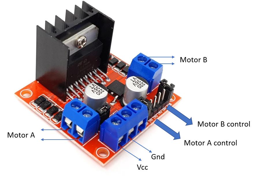
The L298n H-bridge provides independent drive to two motors. It is connected to the motors, the the power source and the microcontroller with the connections summarised below.
| H-Bridge | Connection | Note |
| Motor A | First motor positive and negative terminals | |
| Motor B | Second motor positive and negative terminals | |
| Vcc | Battery positive terminal | |
| Gnd | Battery ground terminal | Ensure the ground is shared with the microcontroller |
| ENA | Pi pin 33 (PWM1) | Motor A PWM control pin |
| IN1 | Pi pin 37 (GPIO 25) | Motor A direction 1 enable |
| IN2 | Pi pin 36 (GPIO 27) | Motor A direction 2 enable |
| IN3 | Pi pin 31 (GPIO 22) | Motor B direction 1 enable |
| IN4 | Pi pin 29 (GPIO 21) | Motor B direction 2 enable |
| ENB | Pi pin 32 (PWM0) | Motor B PWM control pin |
When buying a pre-built L298n on eBay, as I have, the ENA and ENB pins are shorted high using a jumper. With the jumper present the motors will be driven at 100% duty cycle. Precise speed control is only possible when the jumpers are removed and the ENA and ENB pins controlled with a PWM from a microcontroller.
An additional jumper are found behind the power connection block. Removing this jumper disables the built-in 5V regulator. For this project it will remain in place.
IMU
The last component to connect to the Raspberry Pi is the IMU. The chosen IMU for this project is the MPU6050. This IMU is cheap, easy to obtain and provides sufficient accuracy for the project.
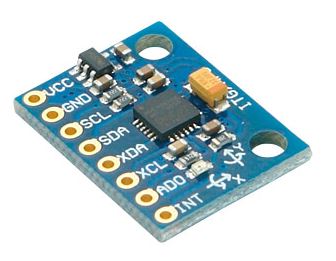 I2C will be used to communicate between the Pi and the IMU. The pins of the MPU6050 is clearly marked and are connected as below.
| MPU6050 | Raspberry Pi |
| VCC | Pin 1 (3.3V) |
| GND | Pin 6 (Ground) |
| SCL | Pin 5 (SCL) |
| SDA | Pin 3 (SDA) |
Assembly
The assembly video was made prior to realising the DC-DC converter is missing. Here is the underside of the top layer with the DC-DC converter and IMU side-by-side.

Setting up the Raspberry Pi
With everything connected, the last remaining step is to get the Raspberry Pi running and able to communicate with the IMU and driving the motors.
Setting up a Pi is covered in detail elsewhere on the web and maybe in the future we go into more detail ourselves on Karooza. For now, I dowloaded the Raspberry Pi Imager and used it to setup Raspberry Pi OS (previously called Raspbian) on the SD card. As none of the usual Pi application will be used these were not installed. As with the E-ink notification and weather display a headless setup, not including the Raspberry OS desktop in the installation, could also have been used. For now, however, this has been kept. To ease updating and retrieving code I installed TightVNC for remote desktop control and WinSCP for file transfer on a Windows PC where most of the development will be done.
Communicating with the IMU
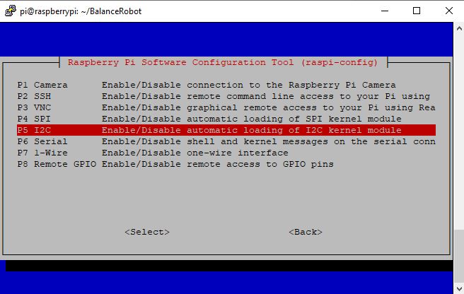
The IMU uses I2C for communication. By default this is disabled on most Pi installations and the Raspberry Pi configuration needs to be run to switch it on. In the console run
sudo raspi-config
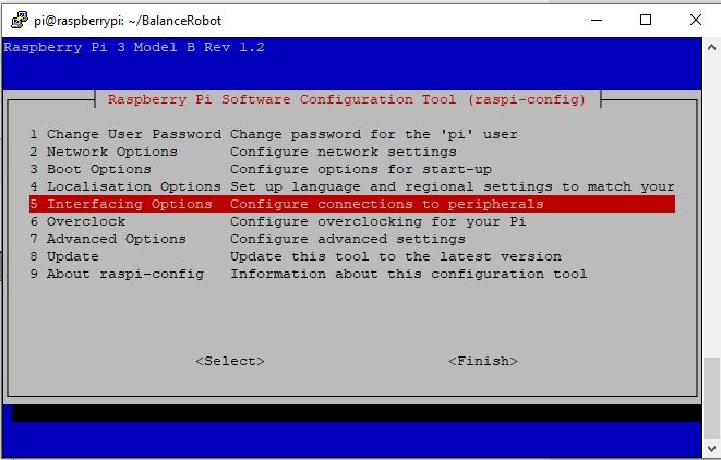 In the configuration move down to ‘Interfacing Options’.
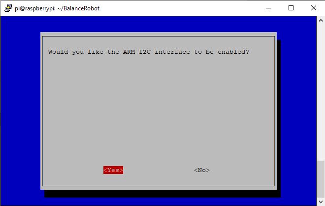 On the next screen select ‘Yes’. Navigate out of the configuration back to the command line and reboot the Pi to finish enabling I2C.
sudo reboot
After the reboot some test code can be used to check that the IMU can be read. I have used code from ElectronicWings for this step.
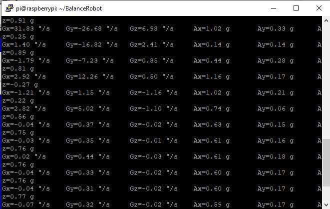 Success, communication with the IMU established with values being updated as the IMU is moved.
Driving the motors
Testing that the motors are working and correctly connected is slightly easier and is done with the piece of code below. By changing the direction pin values and the duty cycle we can check that the motors are behaving as expected for use with our future control system.
import RPi.GPIO as GPIO
import time

#H-Bridge A / Motor A
hbAIn1 = 37
hbAIn2 = 36
enaA = 33

#H-Bridge B / Motor B
hbBIn1 = 31
hbBIn2 = 29
enaB = 32

#Setup pins motor A
GPIO.setmode(GPIO.BOARD)
GPIO.setup(hbAIn1,GPIO.OUT)
GPIO.setup(hbAIn2,GPIO.OUT)
GPIO.setup(enaA,GPIO.OUT)
pwmEnaA = GPIO.PWM(enaA,1000) #1000Hz switching frequency
pwmEnaA.start(75) #duty cycle

# #Setup pins motor B
GPIO.setup(hbBIn1,GPIO.OUT)
GPIO.setup(hbBIn2,GPIO.OUT)
GPIO.setup(enaB,GPIO.OUT)
pwmEnaB = GPIO.PWM(enaB,1000) #1000Hz switching frequency
pwmEnaB.start(100) #duty cycle

# #Motor A forward
GPIO.output(hbAIn1,GPIO.LOW)
GPIO.output(hbAIn2,GPIO.HIGH)

# #Motor B forward
GPIO.output(hbBIn1,GPIO.HIGH)
GPIO.output(hbBIn2,GPIO.LOW)

time.sleep(5)
GPIO.output(hbAIn1,GPIO.LOW)
GPIO.output(hbAIn2,GPIO.LOW)
GPIO.output(hbBIn1,GPIO.LOW)
GPIO.output(hbBIn2,GPIO.LOW)
#pwmEnaB.ChangeDutyCycle(50)
time.sleep(1)
GPIO.cleanup()
Next steps
The overall project of investigating modelling and control using an inverted pendulum is progressing well. The physics model of the robot is ready, waiting for the weight and height parameters from the the real robot described here. The next step is to validate and calibrate the Simulink model previously developed, complete the Raspberry Pi code to calculate the robot’s tilt angle and lastly develop the control algorithms to balance the robot.

2 thoughts on “How to contruct a self-balancing robot”