
If you are looking for a STM32F3 board for your next project it might just be worth your while to consider the SP Racing F3 board. In a previous post I discussed how you can program an old Naze32 flight controller board using Arduino. While writing it I also looked at some other low cost flight controller boards out there. One board which I could not ignore was the SP Racing F3 board. These boards normally sell for less than the Naze32 even though it has an F3 processor onboard (compared with F1 from the Naze32)! So I ordered one from Banggood for a few cents less than €13 to try it out.
What you get
The brains on the board is the STM32F303CCT6 which has an ARM Cortex M4 core with 256KB of flash memory and 40KB of SRAM. Among other things it also boasts a FPU (Floating Point Unit) and four 12bit 5MSPS ADC’s!
As it’s a flight controller board it also comes with a MPU6050 IMU which includes a 3-axis gyroscope and a 3-axis accelerometer connected through the I2C bus. Additionally you also get 8MB of SPI connected flash memory and a SiLabs CP2102 USB to UART bridge.

The board measures 36mm x 36mm with mounting holes spaced 30.5mm apart.
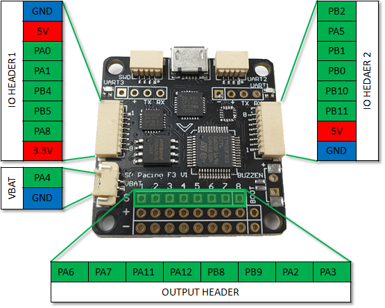
Pin-out
Unlike the Naze32 not all pins are broken out to 2.54″ headers. A lot of them are broken out to JST-SH (1mm pin pitch) connectors which reduces the fine soldering work that is typically required. This also helps to make the board more compact and it typically comes with a set of cables. The pins of the STM32F303 are broken out like this:
Powering the board
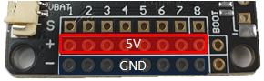
Like most of these flight controller boards the primary way of powering them is through the ESC (Electronic Speed Controller) output header. This is because typically ESC’s also have a small regulator (sometimes referred to as BEC) which can be used to power the board. If your ESC does not have a BEC or you are using the board for some project that does not even have an ESC then you can still just power the board through this header by a applying 5V to the center pin.
When you program the board you can also power it through the USB connector.
Special Function Pins
Not all pins can be accessed directly, some are wired to drive some special circuits. These pins I just refer to as special function pins. Below are some of these pins.
LED
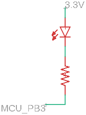
The board has a builtin small red LED which is wired to pin PB3. Take note that the pin sinks current through the LED so taking the pin high will switch the LED off.
Buzzer (Open collector)
You will notice that there is a 2 pin header marked “Buzzer”. As you can guess it is intended to drive a small buzzer (max 50mA) from pin PC15. 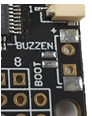 The circuit is basically a small transistor which has it’s base connected to PC15, emitter to ground and collector to the header pin marked negative. So by placing a buzzer between the positive header pin (which is connected to 5V) and this buzzer negative pin you can drive it with pin PC15. You can obviously also use it to drive something else as long as you stay below the 50mA current limit. The circuit looks something like this:
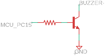
VBAT
The 2 pin JST-SH connector marked VBAT drives a voltage divider circuit which has pin PA4 connected in the middle. The circuit consists of a 10k and 1k resistor to create a divide by 11 function with the output on pin PA4. As you might guess this is typically used to measure the voltage level of the battery used to power the aircraft (or in this case your project).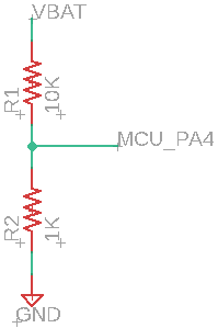 Tip: Arduino often defaults to 10bit resolution when reading the ADC. Since the MCU has a 12bit ADC remember to set it explicitly (see the example program at the end).
BOOT Pins
Next to the output header (8×3 header) you can see two pins marked “BOOT”, this is just a pad to the Boot0 pin and 3.3V. By shorting out these two pins and powering the board the MCU will boot to it’s builtin system bootloader. This will then allow you to upload your custom programs.
MPU6050
The MPU6050 is connected to the MCU through the I2C1 bus.
8MB Flash Memory
The Winbond 25Q64JVSIQ 8MB Flash memory chip is connected through SPI2.
CP2102 and UARTS
The CP2102 is connected to UART1 PA9 (TX) and PA10 (RX). UART1 is also broken out to 2.54″ headers and a JST-SH connector on the bottom of the board. You can obviously not use all three at the same time.
UART2 is on pins PA14 (TX) and PA15 (RX) but also shared with the SWD connector and can’t be used at the same time.
As for UART3, it’s on pins PB10 (TX) and PB11 (RX) which is also broken out to IO Header 2.
Configure Arduino IDE
When we previously looked the Naze32 board we used the Arduino_STM32 core. Unfortunately this core does not have good support for F3 boards so we have to take another route. This time we will use STM32duino which is officially supported by ST. To install it you have to first go to File -> Preferences and in the Settings tab add:
https://github.com/stm32duino/BoardManagerFiles/raw/master/STM32/package_stm_index.json
to the Additional Boards Manager URLs. Then go to Tools -> Board -> Boards Manager… and type “STM32” you should see “STM32 Cores by STMicroelectronics”. Select it and install it.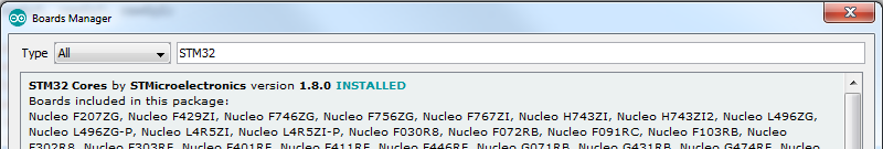
Once you are done you should be able to see a “STM32 Boards” section under the Tools -> Board drop-down (you might need to scroll down a bit).
Next you need to download and install STM32CubeProgrammer from STMicroelectronics. This installs some additional dependencies which are required. You might be prompted to provide an email address which they will use to send you a link when you download it. Once this is done you are ready to start writing code and programming the board.
Programming the board
Once you have configured your Arduino IDE you can program the board using the “Generic STM32F3 Series” board with upload method “STM32CubeProgrammer(Serial)”. Before you program the board remember to first power cycle (disconnect and connect the USB cable) it while shorting the “BOOT” pins next to the output header (8×3 header). You can just use a short jumper cable or solder a small push button to the pins. Oh and I assume you understand that this will overwrite any existing firmware on the chip, so if you want to use the board later again as a flight controller you will need to reprogram it with the original firmware.
Example Program
Below is just a quick program/sketch that a put together to get you started (it was done real quick so don’t judge).
#include <Wire.h>
#include <SPI.h>

#define ADDR_MPU_6050     0x68
#define PIN_FLASH_CS      PB12

// Use SPI2 bus (for flash memory)
SPIClass SPI_2(PB15,PB14,PB13);

void setup()
{
  pinMode(PIN_FLASH_CS, OUTPUT);

  // Set most pins to digital output pins
  // LED
  pinMode(PB3, OUTPUT);

  // 8X3 HEADER
  pinMode(PA6, OUTPUT);
  pinMode(PA7, OUTPUT);
  pinMode(PA11, OUTPUT);
  pinMode(PA12, OUTPUT);
  pinMode(PB8, OUTPUT);
  pinMode(PB9, OUTPUT);
  pinMode(PA2, OUTPUT);
  pinMode(PA3, OUTPUT);

  // IO HEADER 1
  pinMode(PA0, OUTPUT);
  pinMode(PA1, OUTPUT);
  pinMode(PB4, OUTPUT);
  pinMode(PB5, OUTPUT);
  pinMode(PA8, OUTPUT);

  // IO HEADER 2
  pinMode(PB11, OUTPUT);
  pinMode(PB10, OUTPUT);
  pinMode(PB0, OUTPUT);
  pinMode(PB1, OUTPUT);
  pinMode(PA5, OUTPUT);
  pinMode(PB2, OUTPUT);

  // Buzzer
  pinMode(PC15, OUTPUT);

  Serial.begin(57600);

  // Enable 12bit ADC resolution
  analogReadResolution(12);

  // Configure I2C and initialize MPU6050
  Wire.begin();
  Wire.setClock(400000);
  MPU6050_Init();

  // Configure SPI2 and flash CS pin
  SPI_2.begin();
  SPI_2.setBitOrder(MSBFIRST);
  SPI_2.setDataMode(SPI_MODE0);
  SPI_2.setClockDivider(SPI_CLOCK_DIV16); // SPI clock of 72/16 = 4.5MHz
  digitalWrite(PIN_FLASH_CS, HIGH);       // Active low, so deselect Flash chip
}


void loop()
{
  // Toggle the LED and Buzzer
  digitalWrite(PB3, HIGH);
  digitalWrite(PC15, HIGH);
  delay(1000);
  digitalWrite(PB3, LOW);
  digitalWrite(PC15, LOW);
  delay(1000);

  // Read VBAT
  Serial.println("VBat:");
  uint32_t adc = analogRead(PA4);
  float vbat = adc * (3.3 / 4096) * 11;
  Serial.println(adc);
  Serial.println(vbat);

  // Get readings from the MPU6050
  float MPU6050_Values[7];
  MPU6050_Read(MPU6050_Values);
  Serial.println("IMU Values:");
  for (int i = 0; i < 7; i++)
  {
    Serial.print(MPU6050_Values[i]);
    Serial.print(" ");
  }
  Serial.println("\n");

  // Read the flash memory chip
  Serial.println("Flash JEDEC:");
  FlashReadJEDEC();

  Serial.println("---\n");
}


void MPU6050_Init()
{
  // Wake MPU-6050
  // Write to the PWR_MGMT_1 register (6B hex)
  Wire.beginTransmission(ADDR_MPU_6050);
  Wire.write(0x6B);
  Wire.write(0x00);
  Wire.endTransmission();

  // Set the full scale of the gyro to +/- 250 degrees per second
  // Write to the GYRO_CONFIG register (1B hex)
  // Set the register bits as 00000000 (250dps full scale)
  Wire.beginTransmission(ADDR_MPU_6050);
  Wire.write(0x1B);
  Wire.write(0x00);
  Wire.endTransmission();

  // Set the full scale of the accelerometer to +/- 4g.
  // Write to the ACCEL_CONFIG register (1C hex)
  // Set the register bits as 00001000 (+/- 4g full scale range)
  Wire.beginTransmission(ADDR_MPU_6050);
  Wire.write(0x1C);
  Wire.write(0x08);
  Wire.endTransmission();

  // Set some filtering to improve the raw data.
  // Write to the CONFIG register (1A hex)
  // Set the register bits as 00000011 (Set Digital Low Pass Filter to ~43Hz)
  Wire.beginTransmission(ADDR_MPU_6050);
  Wire.write(0x1A);
  Wire.write(0x03);
  Wire.endTransmission();
}


void MPU6050_Read(float *MPU6050_Values)
{
  float GyroConversion = 131.0;
  float AccelConversion = 8192;
  int16_t rawAcX, rawAcY, rawAcZ, rawTmp;
  int16_t rawGyX, rawGyY, rawGyZ;

  Wire.beginTransmission(ADDR_MPU_6050);
  Wire.write(0x3B);
  Wire.endTransmission();
  Wire.requestFrom(ADDR_MPU_6050, 14);                   // Request 14 bytes from the sensor
  rawAcX = Wire.read() << 8 | Wire.read();               // Read accelerometer values
  rawAcY = Wire.read() << 8 | Wire.read();
  rawAcZ = Wire.read() << 8 | Wire.read();
  rawTmp = Wire.read() << 8 | Wire.read();               // Read temp value
  rawGyX = Wire.read() << 8 | Wire.read();               // Read gyro values
  rawGyY = Wire.read() << 8 | Wire.read();
  rawGyZ = Wire.read() << 8 | Wire.read();

  MPU6050_Values[0] = rawAcX / AccelConversion;
  MPU6050_Values[1] = rawAcY / AccelConversion;
  MPU6050_Values[2] = rawAcZ / AccelConversion;
  MPU6050_Values[3] = (rawTmp / 340.0) + 36.53;
  MPU6050_Values[4] = rawGyX / GyroConversion;
  MPU6050_Values[5] = rawGyY / GyroConversion;
  MPU6050_Values[6] = rawGyZ / GyroConversion;
}


void FlashReadJEDEC()
{
  // Reads the JEDEC assigned Manufacturer ID byte for Winbond which is EFx0 or 239
  // This is just to verify that that we can access the flash memory on the board
  uint8_t Manufacturer_ID;
  uint8_t MemType;
  uint8_t MemCapacity;

  // Reference: Section 8.3.12 or page 47 of Winbond datasheet
  digitalWrite(PIN_FLASH_CS, LOW);

  SPI_2.transfer(0x9F);
  Manufacturer_ID = SPI_2.transfer(0xFF);
  MemType = SPI_2.transfer(0xFF);
  MemCapacity = SPI_2.transfer(0xFF);

  digitalWrite(PIN_FLASH_CS, HIGH);

  Serial.println(Manufacturer_ID);    // Prints 239
  Serial.println(MemType);            // Prints 64
  Serial.println(MemCapacity);        // Prints 23
}
Conclusion
I find these flight controller boards real handy for my projects. They are normally well priced, already comes with the USB to UART converter (so no extra FT232 board to program or interface with your PC) and as a bonus you get a decent IMU chip.
Hope this post could be insightful and useful for your future projects.