
The Naze32 is one of those iconic flight controller boards of the early days of FPV quads. It superseded the 8bit boards of the time and was the board to have. Fast forward to today, flight controller firmware has generally become much more complex with support for new features and increased flight performance. This left the STM32F1 chip on the Naze32 falling short on flash memory and processing power which caused many firmware’s to drop support for it. As the board was so popular a lot of them were manufactured and today you can get them relatively cheap, you might even have one laying around from earlier times. Although these boards can’t run the latest and greatest flight control firmware they are still very powerful and make for a perfect development board for your projects! So in this post we will look at how you can revive your old Naze32 and program it using Arduino.
Naze32 Overview
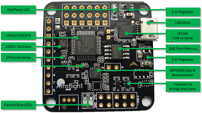
What you get in terms of hardware on a Naze32 depends on which version of the board you have. I will be looking at revision 6 with sensors for 6DOF (Degrees Of Freedom) since they are normally the cheapest and easiest to come by. On the Rev.6 board you get the following components:
- STM32F103CBT6 Microcontroller, this 32bit controller runs up to 72MHz and has 20Kb of SRAM and 128Kb flash memory for your programs.
- CP2104 USB to Serial converter
- 2MB External Flash connected through SPI (Winbond W25Q16JV)
- MPU6500 IMU which includes a 3-axis accelerometer and 3-axis gyro
- Two 3.3V regulators, one for the MCU and one for the sensors
The board measures 36mm x 36mm with mounting holes 30.5mm x 30.5mm apart.
Setup Arduino IDE
To program the board you can use the Arduino_STM32 core, also known as “Rogers Core”. The steps to install the core was discussed in a previous post but I will go over it again as there are some additional steps required for this board.
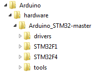
So I am assuming you already have the Arduino IDE installed, the next thing to do is download the Arduino_STM32 core and extract it to your ..\Documents\Arduino\hardware folder. If the hardware folder does not exist you will have to create it first. After extracting the folder tree should look something like this:
Most of the development boards supported by the core uses a 8MHz oscillator but the Naze32 uses a 12MHz oscillator which means that if you try to use one the “Generic STM32F103C series” boards it will not work. To solve this we have to add our own board and adapt it for a 12MHz oscillator. So start by opening “boards.txt” in your ..\Documents\Arduino\hardware\Arduino_STM32-master\STM32F1 folder with a text editor like Notepad or Notepad++. Look for the section marked “Generic STM32F103C”, select the whole section, copy it and past it just above the original section.
###################### Generic STM32F103C ########################################

genericSTM32F103C.name=Generic STM32F103C series
genericSTM32F103C.vid.0=0x1EAF
genericSTM32F103C.pid.0=0x0004
genericSTM32F103C.build.variant=generic_stm32f103c
...
Next change the name of the section to “Naze32 Rev6” (the row with hash signs as well as the “genericSTM32F103C.name=” entry). Then set “genericSTM32F103C.build.variant=” to “naze32_rev6”. After that you can use the Find & Replace feature and replace “genericSTM32F103C” with “naze32Rev6” (but only in this new section you created!). Below are the first and last couple of lines to illustrate:
###################### Naze32 Rev6 ###############################################

naze32Rev6.name=Naze32 Rev6
naze32Rev6.vid.0=0x1EAF
naze32Rev6.pid.0=0x0004
naze32Rev6.build.variant=naze32_rev6
...
naze32Rev6.menu.opt.ogstd.build.flags.optimize=-0g
naze32Rev6.menu.opt.ogstd.build.flags.ldspecs=
We will only configure the board for using a 72MHz clock so you can also comment the other CPU clock lines like this:
#-- CPU Clock frequency
naze32Rev6.menu.cpu_speed.speed_72mhz=72Mhz (Normal)
naze32Rev6.menu.cpu_speed.speed_72mhz.build.f_cpu=72000000L

#naze32Rev6.menu.cpu_speed.speed_48mhz=48Mhz (Slow - with USB)
#naze32Rev6.menu.cpu_speed.speed_48mhz.build.f_cpu=48000000L
When you are done you can save and close the file.
Now you need to make a copy of the generic_stm32f103c folder in the ..\Documents\Arduino\hardware\Arduino_STM32-master\STM32F1\variants folder and rename it to “naze32_rev6”. In this new folder open the “boards_setup.cpp” file in the wirish folder. Look for the following line:
	#elif F_CPU==72000000
		#define BOARD_RCC_PLLMUL RCC_PLLMUL_9
and modify it to read:
	#elif F_CPU==72000000
		#define BOARD_RCC_PLLMUL RCC_PLLMUL_6
Save the file.
This changes the PLL multiplier to get 72MHz from a 12MHz oscillator.
Then finally you can update the pin assigned to the build in LED by editing the “..\STM32F1\variants\naze32_rev6\variant.h” and “..\STM32F1\variants\naze32_rev6\board\board.h” files:
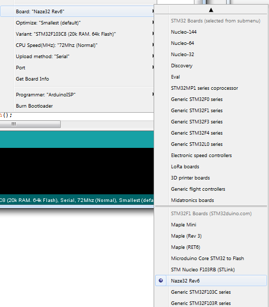
#define LED_BUILTIN PB4Restart the Arduino IDE and look for the new Naze32_rev6 board:
Using the Naze32
The image below shows how the pins of the microcontroller is broken out on the board. I tried to color code the labels to clearly show pads which are for power, ground, GPIO or has some special function.

Note that the board does not have any 5V regulators. In the above diagram when we refer to 5V it’s actually the voltage supplied to the board, which should normally be 5V.
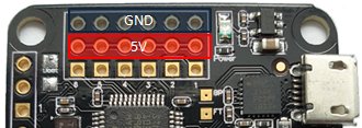
Powering the board
The two most popular ways to power the board is through the USB connector or through the PWM header (3×6) located at the front of the board. As there is a small diode OR circuit it is also possible to power the board with both sources at the same time. When using the PWM header apply 5V to any of the pins in the middle row and ground to the top row.
GPIO pins
Most of the GPIO pins that we can access are on the PWM header in the front as well as on the single header to the left of the board. The remaining few are scattered throughout the board and some are only available through SMD pads.
The pins broken out to the PWM header are all directly connected to the microcontroller while the pins on the left header have a 1k protection resistor between them and the microcontroller.
Special Function pins
There are some pins which are intended to drive external peripheral and has these driving circuits already onboard. These pins you can not directly use as GPIO pins and therefore I just call them special function pins. Most of these pins are located on the 2×5 header on the bottom of the board.
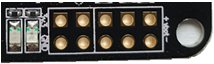
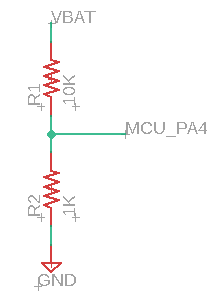
The two pins on the right of the 2×5 header are connected to a voltage divider circuit which is internally connected to pin PA4 of the microcontroller. Originally the intention of this voltage divider was to measure the flight battery voltage. It has a 10k and 1k resistor to create a divide by 11 function which can be read from pin PA4.
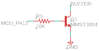
Next to the voltage divider pins we have a 5V pin and a pin connected to the collector of a transistor which is driven internally by PA12. The transistor can sink up to about 200mA and is normally intended to drive a small piezo buzzer.
Then the following two pins are PA9 but inverted and ground. PA9 is also UART1 TX and was originally used to drive telemetry through an FRSky RC receiver which used inverted UART signals.
The next set of pins are SDA and SCL for the I2C2 bus or can also be remapped to UART3 TX and RX.
The last two pins on the 2×5 header are 3.3V and ground. Note that the regulators on this board is not the most powerful, so I would not take much more than 100mA from these pins.
Bootloader Jumper
On the top left of the board is a small SMD jumper which you can use to enable the system bootloader. The easiest is to just solder a switch to these pads that you can close when programming the board. If you are unfamiliar with STM32F1 boards, you need to power the board up while having this jumper (BOOT0) closed. This will cause the board to start it’s internal bootloader which will allow you to upload your programs via the UART1 serial port.
MPU6500 pins
The MPU6500 is connected through I2C2 pins PB10 (SCL) and PB11 (SDA).
Flash memory pins
The flash memory chip (Winbond W25Q16JV) is connected to the SPI2 pins PB12 (CS), PB13 (Clock), PB14 (MISO) and PB15 (MOSI).
LED Pins
The two LED’s on the board are on pins PB4 (red) and PB3 (green) which is by default used for JTAG, to be able to use them you have to first call disableDebugPorts() in setup() function of your code. The pins sink current so to switch a LED on you have to pull the pin low.
Example Program
Below is just a quick program/sketch I put together to show the basics and how to access the other devices on the board. When you want to program the board remember to power the board with the BOOT0 jumper closed and then using the “Serial” Upload Method.
#include <Wire.h>
#include <SPI.h>

#define PIN_LED0          PB4             // Red
#define PIN_LED1          PB3             // Green
#define ADDR_MPU_6500     0x68
#define PIN_FLASH_CS      PB12
#define PIN_VBAT          PA4
#define PIN_BUZZ          PA12

// Use I2C2 pins
TwoWire Wire2(2, I2C_FAST_MODE);
#define Wire Wire2

// Use SPI2
SPIClass SPI_2(2);


void setup()
{
  disableDebugPorts();                    // Allow us to use PB3 and PB4 as GPIO pins
  pinMode(PIN_LED0, OUTPUT);
  pinMode(PIN_LED1, OUTPUT);
  pinMode(PIN_FLASH_CS, OUTPUT);
  pinMode(PIN_BUZZ, OUTPUT);
  digitalWrite(PIN_LED0, HIGH);           // Make sure LED is off
  digitalWrite(PIN_LED1, HIGH);           // Make sure LED is off
  digitalWrite(PIN_FLASH_CS, HIGH);       // Active low, so deselect Flash chip
  digitalWrite(PIN_BUZZ, LOW);

  Wire.begin();
  Wire.setClock(400000);
  MPU6500_Init();

  SPI_2.begin();
  SPI_2.setBitOrder(MSBFIRST);
  SPI_2.setDataMode(SPI_MODE0);
  SPI_2.setClockDivider(SPI_CLOCK_DIV16); // SPI clock of 72/16 = 4.5MHz

  Serial.begin(57600);
  Serial.println("Started...");

}

void loop()
{
  // Switch LEDs on and off
  digitalWrite(PIN_LED0, LOW);
  delay(200);
  digitalWrite(PIN_LED1, LOW);
  delay(100);
  digitalWrite(PIN_LED1, HIGH);
  delay(200);
  digitalWrite(PIN_LED0, HIGH);

  // Pull the open collector (buzzer) pin low and high
  digitalWrite(PIN_BUZZ, HIGH);
  delay(200);
  digitalWrite(PIN_BUZZ, LOW);

  // Read the analog voltage via the voltage divider
  Serial.println("VBat:");
  Serial.println(ReadVBat());
  Serial.println("");

  // Get readings from the MPU6500
  float MPU6500_Values[7];
  MPU6500_Read(MPU6500_Values);
  Serial.println("IMU Values:");
  for (int i = 0; i < 7; i++)
  {
    Serial.print(MPU6500_Values[i]);
    Serial.print(" ");
  }
  Serial.println("\n");

  // Read the flash memory chip
  Serial.println("Flash JEDEC:");
  FlashReadJEDEC();

  // Print a line and restart the loop after 1sec
  Serial.println("---\n");
  delay(1000);
}


float ReadVBat()
{
  // Reads the voltage on the analog pin then convert to the
  // actual voltage. Assuming VRef = 3.3 with 12 bit ADC and
  // divide by 10 voltage divider. The correction factor can
  // obviously be a constant.
  uint16_t vbatRaw = analogRead(PIN_VBAT);
  float vbat = (vbatRaw * (3.3 / 4096) * 11.0);
  return vbat;
}


void MPU6500_Init()
{
  // Wake MPU-6500
  // Write to the PWR_MGMT_1 register (6B hex)
  Wire.beginTransmission(ADDR_MPU_6500);
  Wire.write(0x6B);
  Wire.write(0x00);
  Wire.endTransmission();

  // Set the full scale of the gyro to +/- 250 degrees per second
  // Write to the GYRO_CONFIG register (1B hex)
  // Set the register bits as 00000000 (250dps full scale)
  Wire.beginTransmission(ADDR_MPU_6500);
  Wire.write(0x1B);
  Wire.write(0x00);
  Wire.endTransmission();

  // Set the full scale of the accelerometer to +/- 4g.
  // Write to the ACCEL_CONFIG register (1C hex)
  // Set the register bits as 00001000 (+/- 4g full scale range)
  Wire.beginTransmission(ADDR_MPU_6500);
  Wire.write(0x1C);
  Wire.write(0x08);
  Wire.endTransmission();

  // Set some filtering to improve the raw data.
  // Write to the CONFIG register (1A hex)
  // Set the register bits as 00000011 (Set Digital Low Pass Filter to ~43Hz)
  Wire.beginTransmission(ADDR_MPU_6500);
  Wire.write(0x1A);
  Wire.write(0x03);
  Wire.endTransmission();
}


void MPU6500_Read(float *MPU6500_Values)
{
  float GyroConversion = 131.0;
  float AccelConversion = 8192;
  int16_t rawAcX, rawAcY, rawAcZ, rawTmp;
  int16_t rawGyX, rawGyY, rawGyZ;

  Wire.beginTransmission(ADDR_MPU_6500);
  Wire.write(0x3B);
  Wire.endTransmission();
  Wire.requestFrom(ADDR_MPU_6500, 14);                   // Request 14 bytes from the sensor
  rawAcX = Wire.read() << 8 | Wire.read();               // Read accelerometer values
  rawAcY = Wire.read() << 8 | Wire.read();
  rawAcZ = Wire.read() << 8 | Wire.read();
  rawTmp = Wire.read() << 8 | Wire.read();               // Read temp value
  rawGyX = Wire.read() << 8 | Wire.read();               // Read gyro values
  rawGyY = Wire.read() << 8 | Wire.read();
  rawGyZ = Wire.read() << 8 | Wire.read();

  MPU6500_Values[0] = rawAcX / AccelConversion;
  MPU6500_Values[1] = rawAcY / AccelConversion;
  MPU6500_Values[2] = rawAcZ / AccelConversion;
  MPU6500_Values[3] = (rawTmp / 333.87) + 21;
  MPU6500_Values[4] = rawGyX / GyroConversion;
  MPU6500_Values[5] = rawGyY / GyroConversion;
  MPU6500_Values[6] = rawGyZ / GyroConversion;

}


void FlashReadJEDEC()
{
  // Reads the JEDEC assigned Manufacturer ID byte for Winbond which is EFx0 or 239
  // This is just to verify that that we can access the flash memory on the board
  uint8_t Manufacturer_ID;
  uint8_t MemType;
  uint8_t MemCapacity;

  // Reference: Section 8.3.12 or page 47 of Winbond datasheet
  digitalWrite(PIN_FLASH_CS, LOW);

  SPI_2.transfer(0x9F);
  Manufacturer_ID = SPI_2.transfer(0xFF);
  MemType = SPI_2.transfer(0xFF);
  MemCapacity = SPI_2.transfer(0xFF);

  digitalWrite(PIN_FLASH_CS, HIGH);

  Serial.println(Manufacturer_ID);    // Prints 239
  Serial.println(MemType);            // Prints 64
  Serial.println(MemCapacity);        // Prints 21
}
Hopefully you found this post interesting and, now that you are armed with the basics, can also use a Naze32 board in future projects.
PS: The featured image at the top of this post is a Naze32 installed on my self balance robot.
One thought on “Programming Naze32 with Arduino”