
Using CAN bus to connect peripherals on a drone has always sounded like a good idea. It is well known for it’s robustness and efficiency in connecting electrical control units in cars together, so it should also be well suited for drones. Flight controllers like the Pixhawk and Cube have always had a CAN bus interface but was not really used that much. That was, until the UAVCAN project was started and later adopted by ArduPilot which made the CAN bus more accessible to developers. Being an open protocol and very well documented it became easier for people to start developing their own CAN peripheral nodes. At the time of writing this post, version 0 has been implemented in the ArduPilot flight control firmware.
Not being able to contain my curiosity I also started experimenting with UAVCAN and ArduPilot. I discovered the work done by OlliW which really inspired me and gave me a boost in the right direction! One thing lead to another and a few weeks down the line I had a working UAVCAN GPS with compass node!
So in this post I will show you how I did it while also trying to provide some additional information for anyone else wanting to give it a go. In the first few paragraphs I will very briefly explain some concepts that I think would be helpful to know before going onto the building of a node. Also keep in mind that I am not an expert on the subject and only sharing my views, so you might have to take some of the things I say with a grain of salt.
Why CAN
As mentioned before, the CAN (Controller Area Network) bus is widely used on cars and industrial machines to connect different sensors and actuators together. It uses differential signaling to help improve robustness against electromagnetic noise. If you are not familiar with differential signaling, it just means that the signal is sent over two lines with voltage levels in opposite directions. A bit being transmitted is then seen as the voltage difference between the two signals rather than between the signal and ground. The idea is that an interfering signal will influence the voltage level in both lines similarly and therefore the difference would still be the same.

The reason why I also mention this is to help understand why CAN transceiver chips are required. Among other things these devices will convert the ground referenced I/O pin voltages from a microcontroller to differential signal voltages.
Another feature of CAN is that it is a multi-master protocol. This means there is no single master device and all devices can speak whenever they want (well almost), unlike for example I2C where the master has to initiate communication. The advantage of this is that we can truly have a network (as it’s name suggests) of smart nodes that can speak to each other and form a distributed system. The whole system can thus more easily be broken into smaller, self contained units focused on specific tasks. The possibilities that this brings to your drone is really very exciting!
Bytes on the bus are sent in serial frames at up to 1MBit/s. Each frame holds some overhead bits and a maximum of 8 data bytes. The overhead bits includes a node ID which can identify the node on the network and is also used to indicate a priority level. Lower valued ID’s have priority over higher ones . Being able to set the priority of nodes is another nice feature.
Then there is also the reduction in wiring which relates to a cleaner and easier to troubleshoot build. Less wires also reduce the risk of them picking up and distributing noise through the drones electronics. The wire reduction is realized from the idea that CAN nodes are normally smart units and act as kind of a gateway to it’s peripherals. Take as example our GPS with compass node, the GPS module needs a UART bus (at least 2 wires) and the magnetometer uses an I2C bus (another 2 wires). If we also had lights or buttons on the node then we can add some GPIO lines to it as well. Then we still need some wires to power the unit. You can see how quickly the wiring increases. Using CAN we can reduced it to only 4 wires (which includes power wires) and still add many more peripherals to our node. We could then also further save on wiring by daisy chaining nodes behind each other.
How CAN works on a physical level is really very interesting stuff and although you don’t need to know all the details to get the node in this post working, I would still recommend that you look at some more detailed articles on the topic.
UAVCAN on Top
As mentioned above, each CAN frame holds a maximum of 8 data bytes. So if you wanted to send for example some GPS position over the CAN bus which consists of three 32bit values (e.g. latitude, longitude and altitude) it would require 12 bytes. As this would not fit into a single CAN frame we would need to spread it over multiple CAN frames and then manage how the data is broken up and rebuild on the other side. What we really need is another layer on top of the raw CAN frames that can handle these kind on things for us and this is where UAVCAN comes into play.
UAVCAN defines some standard messages or data structures that we can fill and then use the provided functions to break these structures up into CAN frames and send them to the CAN controller. On the other side the CAN frames are read from the controller and passed to the UAVCAN parser which rebuilds the message or data structure for us. So UAVCAN will do all the underlying low level CAN frame handling for us while we read and write higher level messages on the bus.
If there are no standard message that supports the values we want to send then we can also use UAVCAN’s DSDL (Data Structure Description Language) to create custom data structures. But before going down that route just remember that ArduPilot (and other nodes on the network) would also need to be aware of these custom messages.
The few sentences above is just a very crude attempt to explain where UAVCAN fits in. For more details on UAVCAN have a look at their website, the protocol is very well documented.
Building a UAVCAN Node
The bare minimum items required to build a CAN network is at least two nodes connected to the wire bus which is terminated on both ends with 120 ohm resistors.
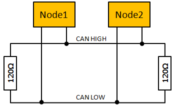
We can add many nodes to the bus but just have to remember that the first and last nodes should terminate the bus through 120 ohm resistors for the bus the function properly. Most of the time the first resistor is already installed on your autopilot’s CAN bus transceiver and we only have to worry about terminating on our side. You might get away with it if you forget one of the resistors but it would increases the time required to switch bit states and negatively influence the reliability of the bus.
The minimum items required to build a node is a CAN bus transceiver, CAN bus controller and a microcontroller. As mentioned earlier, the CAN transceiver converts the differential signal to a single ended signal that is fed to the microcontroller or CAN controller. The CAN controller handles the transmit and receive of frames. Then finally we have the microcontroller which reads or writes data from the CAN controller. On the microcontroller we will then also have the UAVCAN layer and on top of it some firmware that does whatever the node is suppose to do.
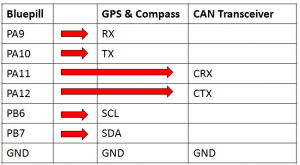
My first node was built using a Bluepill board and it’s a great way to get started at a very low cost. The STM32F103 MCU has a builtin CAN controller which means we only have to add a CAN transceiver. This can be realized by using one of the readily available SN65HVD230 transceiver modules from ebay, the ones I use have “CJMCU-230” silkscreened on the back. These modules also already includes a 120 ohm termination resistor.
On the STM32F103 pins PA11 and PA12 can be used for CAN RX and TX respectively so we wire them directly to the CRX and CTX pins on the transceiver module. The module needs a 3.3V power source which we take from the small voltage regulator on the Bluepill. A GPS module can then be wired to UART1 on PA9 (to GPS RX) and PA10 (to GPS TX), just keep in mind that you might also want to use these pins later for programming so it might be a good idea not to solder them directly. If you have a magnetometer connect it to the I2C pins PB6 (to mag SCL) and PB7 (to mag SDA). All wired up it should look something like this:

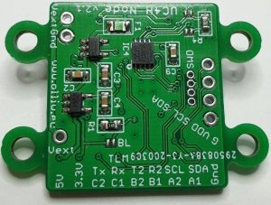
Although the Bluepill solution works, I wanted something a bit more compact and elegant. Not in the mood to reinvent the wheel I went with OlliW’s UC4H General Purpose node. Looking at his schematics, it’s clear that he has put a lot of thought into his design. He used a more modern CAN transceiver chip and added small things like a poly fuse and voltage regulators with built-in reverse battery protection that just makes it a nice and robust solution. The termination resistor is also on the node and can be enabled or disabled by closing two small solder jumpers.
The poly or resettable fuse is a nice touch since all the nodes on the CAN bus share the same power source. Should it happen that any one of the nodes malfunction and cause a short it is handled locally on the node and does not bring the hole bus down with it.
So I downloaded OlliW’s Eagle files from GitHub, generated the Gerber files, had some PCBs manufactured and ordered the components from DigiKey. I kept most things the same and only upgraded the STM32F103T8 he used with the STM32F103TB as it has double the flash memory (128Kb). The reasoning for this is that I want to run AP_Periph on it and therefore the extra space would be very welcome.
The PCB’s have components on both sides so I used my modified pizza oven to reflow solder the parts on the top and a hot air rework station to solder the parts on the bottom. When ordering the PCB’s I also had stencils made for the top and bottom which greatly eases the application of solder paste. The whole assembly process was easier then expected since I normally shy away from these no-lead type packages.

If you don’t feel like building these nodes yourself you can also buy them from jDrones.
Once you have your node you can wire it up as shown below:

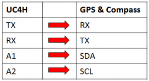
Remember, to close the termination resistor jumpers if the node will be on the end of the bus.
Getting the Firmware
Here you have a couple of routes to choose from:
Roll your own
If you feel adventurous you could use something like libcanard and write your own code for the node. This is a good way if you want to really get into the details of UAVCAN and would allow you to do some custom things. I went this route with my first UAVCAN node and although I got it working in the end I must say I would not recommend it if you are just starting out. Rather take one of the other options below and first get everything working and then come back to this option.
OlliW’s UC4H
Have a look at OlliW’s GitHub page, he has the binaries there ready to be flashed. I have to admit, I have not tried it yet but am pretty confident that it will work like a charm.
AP_Periph
Now for the option that I am the most excited over, AP_Periph. If you have ever compiled the ArduPilot firmware for a custom board then you might be familiar with the hwdef.dat system. How it basically works is that you have a file (hwdef.dat) that defines your hardware, you tell it things like which pins is used for I2C, UART, CAN, etc. and also which sensors you have on them. Then before building the code a Python script parses this file and generates the correct headers and long story short you have ArduPilot firmware for your custom flight controller board.
Now what they (Tridge) have done with AP_Periph is to create a similar system for UAVCAN nodes, this means most of the existing peripheral drivers supported by ArduPilot is also available to be used on your UAVCAN node! Furthermore all you need to do is copy one of the existing hwdef.dat files that matches the microcontroller on your node and modify it to your needs! In our case we can even directly use the f103-gps file as it is.
Since we don’t need to modify f103-gps we can use the pre-compiled binary and upload it directly to our node. You will notice that some files have a “_bl” post-fix, this just indicates that it also contains the AP_Periph boot-loader. If you don’t have the boot-loader installed already then use this file when flashing your node. Having the boot-loader installed means that you could update the firmware on your node via CAN, so you don’t have to remove the node each time you want to update the firmware. This is very handy if the node is already installed on your drone.
Flashing the Firmware
Although the popular option is to use a SWD programmer, firmware flashing can also be done using a USB to UART/Serial converter with 3.3V logic lines. On STM’s site you can download the Flash Loader Demonstrator program to flash the board using your USB to UART converter. Pins PA9 and P10 are then connected to the RX and TX lines of the converter.
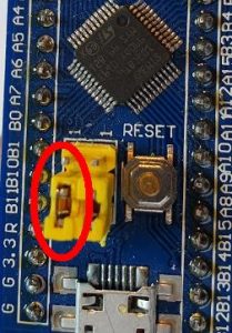
Doing this on the Bluepill means you have to move the boot0 jumper to the 1 position before powering the board and after flashing it move the jumper back.
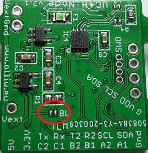
On OlliW’s board, if you use the UART for flashing, there is a small solder jumper for boot0 that you would need to close before flashing and open up again afterwards. Connecting the USB to UART adapter is the same as for the Bluepill, connect node TX to adapter RX and node RX to adapter TX. Oh and don’t forget ground and 5V power.
Testing the Node
So after all this, how do we know if the node works? If you have a flight controller with at least a version of ArduPilot newer than 4 (worked best for me) then you could simply connect it to the CAN bus and try it out. Just remember to set the parameters (GPS_TYPE, etc.) accordingly.
Another option would be to use the UAVCAN GUI Tool available from UAVCAN’s site, but you would then also need a SLCAN adapter. OlliW’s page shows how to build a SLCAN adapter using a Bluepill which is what I am still using very often.
Once your node and the SLCAN adapter is connected, run the UAVCAN GUI Tool. In the connection dialog box select the COM port of the SLCAN adapter and set the Adapter Baud Rate to 1000 000 and click OK. If your adapter is working fine you will be greeted with the window shown below:
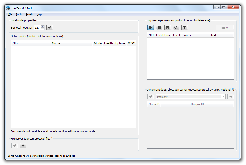
The first thing to do in this window is to click check button next to “Set local node ID” to 127. This will give your SLCAN adapter a node ID so that it’s visible on the network. Next up you would want to use the dynamic node ID server. This is another cool feature of UAVCAN that allows nodes to be assigned an ID dynamically, which can avoid ID conflicts. So to do this, click the rocket button in the “Dynamic node ID allocation server” group. Shortly after you should see the SLCAN adapter and your node appear in the list. In the online nodes group you should then also see your node appear and some basic information on your node. Something like this:

If you get this far then your node is for sure working! You can now double click on your node to see a more detailed information window as shown below:
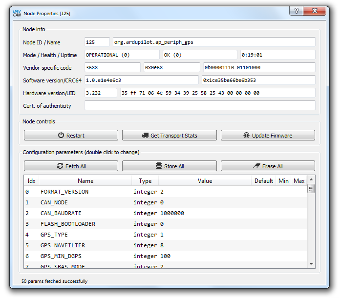
From here you can use the “Fetch All” button to retrieve the parameters of your node. You can also use this window to flash new firmware to your node through UAVCAN.
Another nice tool is the “Bus Monitor” which can be found on the main window under the Tools menu. By clicking the camera button it will log the activity on the bus which you can then view by clicking through the logged lines:

These are just some basic examples of what the UAVCAN GUI tool can do, you can now further experiment with the features of this tool.
In the End
So we reached the end of this very basic introduction to UAVCAN and building of a node. Next you can try to improve it by maybe adding a barometer or neopixel to the node.
UAVCAN on ArduPilot is currently a very active topic and I am sure it will see a lot of progress in the coming months. If you want to be in the loop with the latest development make sure to visit the ArduPilot forum regularly to see whats new.