
If you are like me, you often find yourself opening some electronic device to see what makes it tick and maybe discover some new magic part. Recently this was the case with some new parts that I bought for my FPV drone and could not help noticing how many of these devices used STM micro-controllers. The speed controllers, radio receiver, radio transmitter and even the flight controller had some variant of these 32bit STM micro-controllers on them. Obviously there is something up with these chips and I want in on the secret.
The obvious first step into the STM world would be to get a well documented development board and work your way through it. Browsing online stores and Ebay provided a fairly large variety of development boards for the various chips in the STM32 family. In the end I went the cheap and dirty route and took the Blue Pill which was priced really low and seemed to have an active community behind it.
Board Overview
The board features the STM32F103C8 MCU which is a 32bit ARM Cortex M3 running at 72MHz and provides the programmer with 64kB of flash memory (although mine reported 128kB) and 20kB of RAM.
To put that into context we can briefly compare it to two other popular Arduino boards:
| Feature | Arduino Uno | Arduino Zero | Blue Pill |
| Word size | 8 bit | 32 bit | 32 bit |
| Clock speed | 16 MHz | 48 MHz | 72 MHz |
| Flash memory | 32 kB | 256 kB | 64 kB |
| RAM | 2 kB | 32 kB | 20 kB |
The board provides the MCU with two crystals, the main one clocked at 8MHz and a second at 32.768kHz which is used for the RTC. Then there are some jumpers to select the boot mode, reset button, LEDs, USB connector and headers to which the pins are broken out to. So all in all a very straight forward board that reminds me of an Arduino Nano but only a bit bigger and obviously a whole lot faster.
The pins are broken out in the following way:
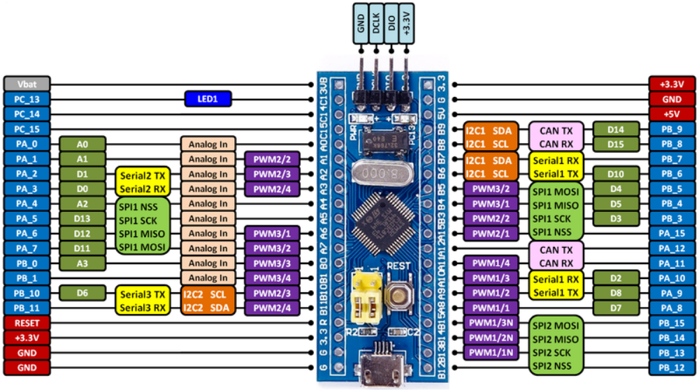
As to why it’s called the Blue Pill, its apparently a reference from the movie The Matrix. It seems that there were initially two variants of the board, one on a blue and one on a red PCB. The former seemed to be slightly better built and became more popular and known as the Blue Pill.
Programming
So the first thing to do is to figure out how to program this thing. From my limited experience with this chip, one of the best things about it is how many options one have for programming it and how easy it is! I have so far discovered 3 options that worked for me:
- Using a USB to Serial converter module
- Using a ST-Link V2 programmer
- Using a USB bootloader
Arduino IDE
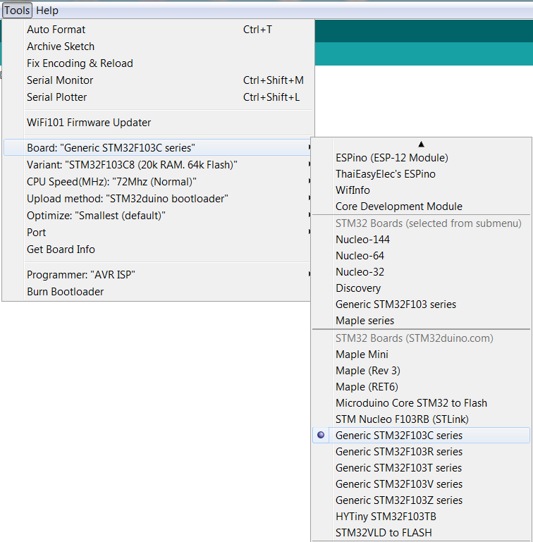
Thanks to some active people in the community we can build and upload our programs using the Arduino IDE. When configuring the IDE one can either use the Board Manager and install STM32 Cores by ST-Microelectronics or use Arduino_STM32. I prefer using Arduino_STM32 and it can be installed by downloading the zip file from here and then extracting it to your ..\Documents\Arduino\hardware folder. Note that if this folder does not exist you would need to create it. After this step restart Arduino IDE (if you had it open during the above steps) and go to Tools->Board and select Generic STM32F103C series. That should take care of the tool-chain, now to the hardware…
Using a USB to Serial module
IMPORTANT: Note that this is a 3.3V MCU and you should set your USB to Serial converter to 3.3V or you would most likely kill it. Since most people have one of these laying around it’s is a pretty good option to start with. The secret here is that the STM32F103 family of devices have a UART bootloader programmed in special ROM memory. So by setting some boot pins on the chip one can force the chip to start in the bootloader mode and then upload your program though UART1. This is why the board also provides the boot mode jumpers, so one would set the jumpers to select if the chip should boot to the bootloader or directly to the program memory. In our case we are only interested in the boot0 jumper (the one closer to the edge of the PCB), when set to 0 the MCU boots to the normal program memory and when set to 1 to the bootloader.
Connecting things up is fairly straight forward:
USB to Serial TX goes to PA10
USB to Serial RX goes to PA9
USB to Serial GND goes to G
USB to Serial 3.3V goes to 3.3V

Note that I am using a custom USB to Serial module and your pins might be different to mine in the image above.
As a test one can then load the Blink sketch from within the Arduino IDE and make sure Generic STM32F103C series is selected under Board, Upload method is Serial and Port is the com port of your USB to Serial module. Before you build and upload move the boot0 jumper to 1 and reset the board (you could also have done it before connecting the board). Now you can proceed to build and upload and if all went well the LED should start blinking! Before you remove the power from the board place the boot0 jumper back to 0 to prevent the board from going into bootloader mode next time it starts up.
Pretty easy isn’t it, but there is even an easier option!
Using a USB bootloader
We have already talked about the UART bootloader that comes installed from the factory but unfortunately the STM32F103 series only comes with this UART bootloader and no USB bootloader. Apparently some of the higher end devices like STM32F4 comes with a USB bootloader and some other interesting options when it comes to flashing firmware. In order to get a USB bootloader onto the F1 chip we would need to flash it ourselves, which turns out to be not so difficult. Basically what we do is to take the bootloader created by Arduino_STM32 and flash it to the chip using the USB to Serial method described earlier. We would still have the UART bootloader (it’s in the ROM so can’t be removed) but the chip would boot to the Arduino_STM32 bootloader and then to your main program. From then on you would not need the USB to Serial module and can program it through USB directly. Something to remember about this option is that the bootloader will also occupy some of the program memory and you would not have the whole 64kB or 128kB available. Luckily it’s not that big and should still leave you with plenty of space available.
So to do this you would need to first download:
STM32duino bootloader (download as zip and extract on your machine)
https://github.com/rogerclarkmelbourne/STM32duino-bootloader
Flash Loader Demonstrator (used to flash the firmware)
http://www.st.com/content/st_com/en/products/development-tools/software-development-tools/stm32-software-development-tools/stm32-programmers/flasher-stm32.html
Then change the boot0 jumper to 1 and connect the USB to Serial board making sure all pins are connected (as explained earlier) and that the 3.3V option is selected on the USB to Serial module.
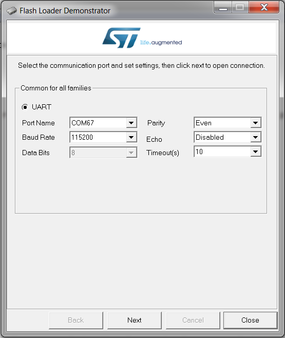
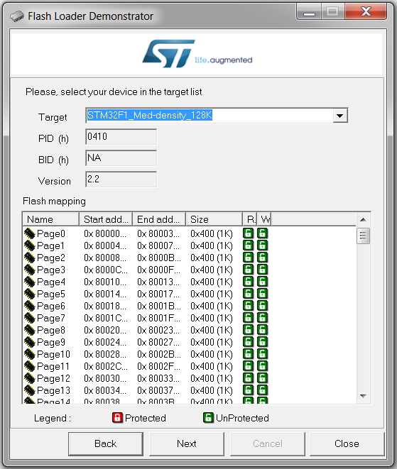
You should then run the Flash Loader Demonstrator program and select the COM port for your USB to Serial module, leave all the other fields as is and click Next.
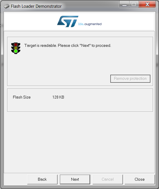
The chip will be read and the flash size indicated (seems some chips have 64kB and some 128kB), you can then click again Next.
Now you can select the target, which in our case is the STM32F1_Med-density_128K and click Next.
In this window select Download to device and provide the path to the firmware file that you downloaded earlier. In my case the path was ..\STM32duino-bootloader-master\binaries\generic_boot20_pc13.bin. You will notice there are a couple of versions, if you look on your board next to the LED the name of the pin that drives the LED is provided and should match the post-fix of the firmware filename. In most cases it would be “_pc13”. When you have selected the file and left the rest of the fields at their default values you can click next to start the upload.

When uploading is completed then remember to change the boot0 jumper back to 0 again.

One final thing left to do now is to install the USB driver for the bootloader. Run the ..\Documents\Arduino\hardware\Arduino_STM32-master\drivers\win\install_drivers.bat file, which would apparently not really install new drivers but rather associated some default windows drivers with the board. After running the file connect your board and check that it installs and configures the driver and shows up in Device Manager as a COM port.

Now you should be all set and ready to upload your programs through the USB bootloader. As a test you can again use the Blink sketch but this time select STM32duino bootloader as Upload method and make sure you select the newly installed Port. Build and upload then check for any error messages and if all went well then the LED should start blinking again.
Maybe you can change the blink rate to make sure it’s not just running a previous blink sketch.
Using ST-link programmer
The two previously discussed methods to upload your programs should be adequate for most basic projects but if you happen to have a ST-Link V2 programmer then you can also use it. The advantage of using the ST-Link SWD programmer is that you have more debugging options which can be very helpful when parts in your program starts going pear-shaped. I bought one of the cheap ones (€6.50) from ebay some time ago and it works perfectly well. All you need to do is connect pins 2,4,6 and 8 (SWDIO, GND, SWCLK, 3.3V) of the programmer to the corresponding pins on the board. In my case the header covered most of the silkscreen which made reading the labels a bit harder. If you have the same problem, the order on mine was from top to bottom GND, SWCLK, SWDIO, 3.3V.

Now all that is left to do is to connect the programmer to your computer select STLink as Upload method then build and upload your sketch.
Conclusion
Although I am also new to the STM32 devices I can already start to get a feeling to why they are so popular. The programming of these devices is in my opinion much easier than the Atmel SAM devices that I am use to. I did not make a study of it but it also appears that the STM32 devices are very well priced which might also be a reason why they are so popular. I for one am very excited about these devices and will for sure be using them more often for my future projects!
2 thoughts on “Getting started with STM32F1”