
A couple of weeks ago I was searching for a cheap brushed flight controller, for a mini quad project, and stumbled upon the Beecore Lite. At 26mm x 26mm this little guy featured a STM32F030 MCU with MPU6050 IMU and a built in RC radio receiver. All this for less than 10 Euro from a local shop! Furthermore the advertisement read that it comes pre-flashed with Silverware firmware and uses the Bayang RC protocol, both of these features were completely new to me. Some forum posts convinced me that Silverware was pretty decent as far as flight control software goes but Bayang was still a problem. I have a FrSky Taranis QX7 which meant that I would not be able to use the built-in receiver, or atleast so I thought until I heard of the MULTI-Module or DIY Multiprotocol TX project.
The DIY Multiprotocol project consists of a hardware module which you can buy many ready made versions (on Ebay, Banggood, etc.) or build one yourself and then the firmware which you can get from the project’s github page. The module then plugs into the module bay or trainer port of your radio and you will then have to select the protocol, bind to the receiver (if needed) and configure the model.
It seems there are two types of modules, some use the ATMega328p and the others the STM32F103 MCU. Apparently the firmware supports more protocols than the flash memory of the ATMega328p can hold and therefore the STM32 option. You can still use the ATMega328p boards but when you compile the firmware you would need to deselect the protocols which you don’t need until the firmware fits.
There are two options for selecting a protocol after you flashed the firmware. The first is by using a 15 position dip switch and the second is by using a serial connection. The serial connection option seems to be the easiest but is not supported by all radios.
So now that I found a way to use the Beecore Lite’s builtin receiver with my radio the next question was, do I buy a MULTI-Module or try to build one myself? The ATMega based modules are really cheap so you would not save much by building one yourself. Nevertheless, after looking at the schematics I felt confident that it would be an easy enough build so I decided to give it a go. Besides, I already had all the parts that was needed and did not feel like waiting 3 weeks for one from China. So ordered the Beecore Lite and started building the module.
Building the module
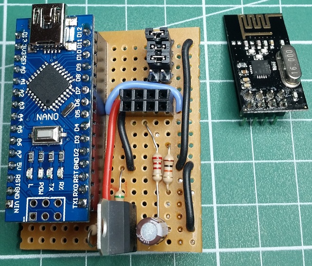
Since I only needed the module for the Bayang protocol I opted for the ATMega328 version. As for protocol selection I opted for the dip switches (which I actually replaced with jumpers), the serial method is available for my Taranis (after uploading the modified firmware) but thought I would leave that for later.
If you download the project from github you can find the schematic in the PCB v2.3d folder. On this schematic 4 different radio modules are shown and depending on the protocols you want to enable you would need to use one or more of them. For the Bayang protocol a NRF24L01 module is required.
Parts
Below is an overview of most of the parts that I used:

Arduino Nano
The small Arduino Pro Mini seems to be a popular choice but I only had some Nano’s laying around.
NRF24L01 module
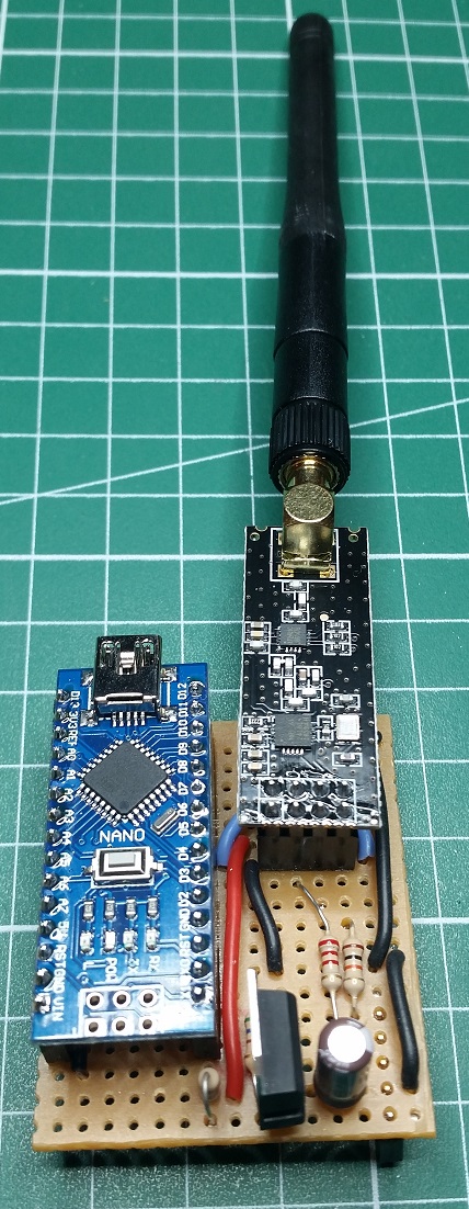
These modules are really cheap and easy to use. I started out with the cheap ones with a integrated PCB antenna and later upgraded to the ones which includes an amplifier and external antenna.
LM317
The module bay provides power directly from the radio battery which is somewhere around 7.2V. The Nano has it’s own little regulator to step the input voltage down to 5V so the LM317 is dedicated to provide the NRF24L01 module with 3.3V. Using the LM317 to produce 3.3V requires a 330 ohm and a 570 ohm resistor. A fixed voltage regulator could reduce the component count but this was all I had at the time.
Couple or resistors
Mostly used for setting the output voltage on the LM317 and for protection against higher than rated I/O voltages on the Nano.
Capacitor
Used a 10uF capacitor with LM317 for a stable output voltage.
Veroboard
To build the circuit on.
Other
To avoid soldering the Nano and NRF24L01 directly to the veroboard I used some PCB female header connectors. For selecting the protocol I used some male headers and a couple of jumpers.
Schematic
Below is the schematic of my board, which is basically a slightly modified and stripped down version of the original:

- J1 is the header connector that plugs into the module bay of the radio.
- The first pin is the PPM output from the radio and has a high state voltage level which is the same as the battery voltage. Therefore it runs through a 10k protection resistor before going to pin D3 on the Nano.
- The 3rd and 4th pins are positive battery supply and ground respectively and is used to power the circuit. The battery supplies the Nano on the VIN pin and also the LM317 which powers the NRF24L01 module.
- Jumpers JP1 to JP4 are the protocol selection jumpers (which normally actually goes to a rotary dip switch) and switch S1 is the binding button. In general the wiring is more or less the same as in the original schematic except for D9 (which I used for the binding switch).
After some time fitting, soldering and cutting tracks I ended up with the board below:


Firmware
Before flashing the firmware I made a couple of changes to the _Config.h and Pins.h files.
Firstly in the _Config.h file I only selected the NRF24L01 radio module and Bayang protocol and also made sure ENABLE_PPM is uncommented. There are also some other interesting options one can change here and it is pretty well documented. Next in the Pins.h file I changed the binding button to PB1 (which is D9 on the Nano) since the default pin (PB5) which is shared with the LED on the Nano did not work so well for me. After these changes I flashed the Nano.
Selecting the protocol
As mentioned earlier, there are more protocols than you can shake a stick at. So what they did was to break it up into banks with 14 protocols per bank. At the time of writing there where 5 banks to choose from. If you scroll to the bottom of the _Config.h file you will see a list of all the banks and the protocols in them. For the Bayang protocol I would need to use bank 3 and protocol number 7.
So first thing I did was to close all 4 jumpers, which would be the equivalent of 15 on a rotary dip switch with ground as common. Then I powered the module up by just connecting the Nano to the USB port and waiting for the LED on the Nano to start flashing. The number of flashes indicates which bank is currently selected. By pressing the bind button I could select the next bank which was confirmed by the increase in LED flash counts. After having selected bank 3 I removed the power from the Nano and only removed the jumper that connected pin A0 to ground. By doing this it would be the equivalent of 7 on the rotary dip switch.
Next I re-installed the NRF24L01 onto the board and plugged the board into the module bay of my radio.

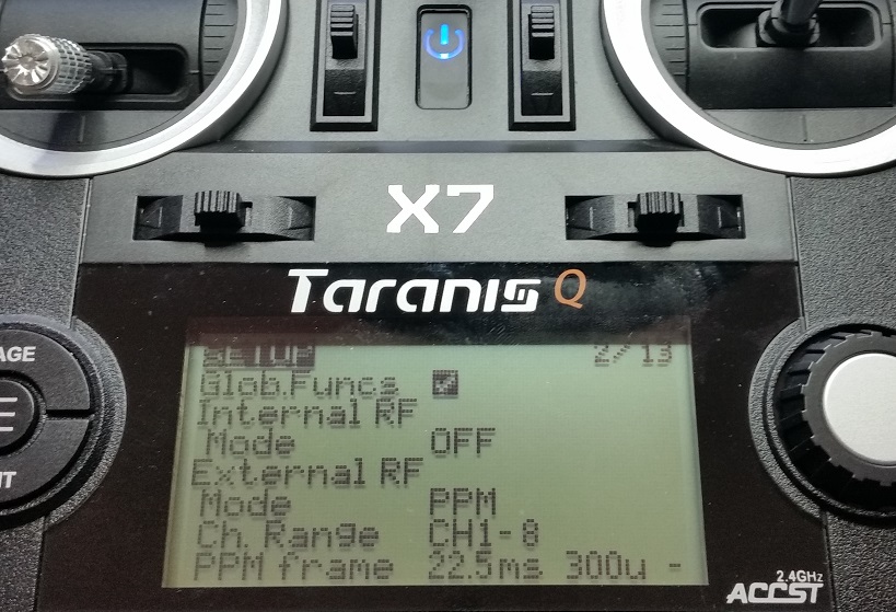
In the model setup of I disabled the internal radio and enabled the external one and set the output mode to PPM.
Testing it out!
By this time the Beecore light board had arrived so it was time to test out my new multi-protocol module. I connected some motors to the Beecore light and gave it power. Then I switched on my radio and about 2 seconds later I could see the Beecore lite had automatically bound to my radio. Then the moment of truth, I increased the throttle and the motors sprung into action! It worked flawlessly!
I also tried it with the more powerful NRF24L01 module and it also performed pretty well. I still need to do a range test to just see how much more range this really gives.
Since then I have completed the build of the mini quad and pushed a good number of batteries through it using this module and not a single time did I have any issues with it. The next step now would be to play with the serial option and also design and 3D print a nice enclosure for it…
A big thanks to the guys who made the effort to create and maintain the DIYMultiprotocolTX project! I would highly recommend anyone needing a non native protocol on their radio to give it a try!
One thought on “Multi-protocol Module for RC Models”