
Maybe you have also looked at some Arduino circuits posted online and noticed an interesting way in how some circuits handle high input pin voltages. With high I mean anything above the typical Vcc + 0.5 rating given in the ATMega328p datasheet.
Lets look at an example, in a previous post I discussed building a multi-protocol module for a RC radio. There we had the scenario where the digital signal from the radio had a high level voltage equal to that of the radio battery voltage. Since the battery voltage of the radio would mostly be above 7V one would think that some voltage level translation would be required before feeding it to the pin. Below is that part of the original circuit:
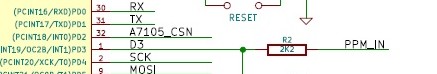
PPM_IN is the signal (around 7V) from the radio and as we can see it only passes through a 2.2k resistor before being connected to pin D3. A natural response to this might be that it would not do any good, the resistor will only limit the current and the pin will still see a too high voltage. You could also take out your multi-meter and confirm this. So why does this work and does it not destroy the pin or even the ATMega328p as a whole?
Well it turns out that the ATMega328p has voltage clamping diodes on each pin, as can be seen in this diagram from the ATMega328p datasheet:
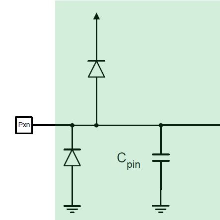
So when the voltage exceeds the rated voltage these diodes will start to conduct and keep the pin voltage within limits. The only catch is that these diodes can not handle very high currents. As the voltage you apply to the pin increases so does the current that these diodes need to conduct to keep clamping the voltage level. This is where the protection resistor comes into play and in the example above its the 2.2k resistor. The resistor limits the current flowing into the pin to below 1mA, which is about the maximum we should allow through the clamping diodes.
The equation for selecting the resistor is pretty straight forward Ohms law stuff. Since we are concerned with the current through the clamping diodes we use the voltage placed across them which boils down to:
Vin – (Vcc + 0.5)
The 0.5V comes from the diodes own forward voltage drop.
Then we use Ohms law with V and I known and say:
R = V/I
R = (Vin – (Vcc + 0.5)) / 0.001
If we wanted to test this with the example we used and say the pin voltage is 7V we get:
R = (7 – 5.5) / 0.001
R = 1500
Since they used a 2.2k resistor it means we are well clear of the 1mA limit and all should be fine. The maximum pin voltage would be:
V = (I x R + (Vcc + 0.5))
V = (0.001 x 2200 + 5.5)
V = 7.7V
A tempting question could now be, how high can we push the pin voltage with this technique. Well, most of the things I described in this post I learned from an Application Note from Microchip and they used this method with 220V AC mains! Not something I would recommend to try at home but the point is, it seems one can go high enough for what most hobby projects would require. The other thing to take from this is that it also protects against voltages going below zero volt. To find the lower voltage limit we use the same process as shown for positive voltages but replace Vcc with 0V. Using our 2.2k resistor example would give:
V = -(I x R + 0.5)
V = -(0.001 x 2200 + 0.5)
V = -2.7V
It seems like it’s general practice for MCU manufacturers to use clamping diodes on the I/O pins so this might work for other MCU’s as well, if we know what current these diodes can handle.
Well that’s it for this post, hope you found it interesting and useful for future projects.