
A couple of months back I stumbled upon Arduboy, a mini handheld game console which draws inspiration from the original Gameboy by Nintendo. As you can deduce from its name it is powered by Arduino. What this means is that it uses an Arduino compatible chip (the ATMega32u4) and can be programmed in the Arduino IDE using the Arduino framework. On top of that Arduboy it is not just hardware, it is also a library or API that makes game development easier and faster on the Arduboy hardware.
Back when I looked at it for the first time I could not justify the price tag. They charged about €50 for the official device which in my head was just an Arduino Leonardo with a screen and buttons. So I gave up on the idea and pursued some other projects. A couple of days ago, by chance I found that there exists a version of the Arduboy library, called Slimboy that works with the ATMega328p. Since I have a drawer full of Arduino Nano’s (which is powered by the ATMega328p) and some OLED screens laying around I thought of trying to build my own Arduboy. So in this article I will share how I built the hardware and programmed a basic Tetris game.
Hardware
On the hardware side you need the following:
Arduino Board
As the idea is to have a handheld console you want to keep things small. Therefore the Arduino Nano makes a lot of sense. Although I have not tried it, it should also work on an Arduino Uno. As long as your board have a ATMega328p microcontroller and Arduino supported bootloader flashed I guess it should work. The Nano’s can be picked up pretty cheap, usually in the range of about €3 on ebay.

OLED Display
Arduboy uses a black and white OLED display with a 128×64 resolution, I am not sure about the physical size but guess it’s either 0.96″ or 1.3″. It is driven by the SSD1306 controller and interfaced through the SPI bus. The modified library (Slimboy) uses the same controller but through the I2C bus which is significantly slower (400kHz vs 8MHz) but apparently well optimized so that it is very useable. So for this reason I used a 0.96″ I2C display. These displays go for about €3 to €4 on ebay and can be identified by only having 4 pins (GND, VCC, SCL, SDA). Normally they can be interfaced using 5V interface lines but just double check when buying. Also make sure it uses the SSD1306 controller.

Buttons
I had two types of tactile switches laying around. Some smaller ones measuring about 6mm x 6mm and some bigger ones measuring about 12mm x 12mm. In the end I went with the smaller ones as the bigger ones just felt and looked too big in comparison with the rest of the device.

LEDs
It is possible to add a RGB led or 3 independent LED’s if you wanted. I didn’t bother with them but it could give a more sleek look!
Speaker
What is a game without sound! To get some noise from the Arduboy it drives a small piezo speaker. The one I used was left over from a previous project and rated for up to 4.6KHz and 30V peak to peak! I wired it in series with a 1k ohm resistor and works fairly well. I think most piezo speakers will work. Just make sure it’s a speaker and not a buzzer which works at a fixed frequency.

Battery
As this is a portable device we inevitably need a battery. Using a Lithium Polymer battery made the most sense. It’s small and light and can deliver more than enough power to run the Nano and screen for a couple of hours. The only thing to consider when working with these batteries are that they are very sensitive for over discharging. Going below about 3.2V could permanently damage the battery. Luckily you can get these batteries with a built-in BMS (Battery Management System) which would automatically cut the power if you over discharge them. So when picking a Lithium Polymer battery make sure you have one with this protection circuit. You could also use Lithium Ion batteries which are very similar and actually considered a bit safer.
The other issue is charging the battery. To keep things simple I got a cheap USB charger for the battery. I also made it possible to detach the battery from my Arduboy when it needs a charge. When fully charged the battery sits at about 4.2 volts.

Notice the small protection (BMS) circuit at the top of the battery.
Boost Converter
Since the Lithium Ion battery can only supply up to 4.2V and while in use can drop to almost 3.2V we have a small problem. When powered externally, the Nano requires between 7V and 12V. So to solve this issue I used a cheap adjustable boost converter (steps the voltage up) based on the MT3608 chip. Before soldering it I first adjusted the output voltage to 7.5V. This particular model can go up to 28V so just be careful.

Building it up
Below is a quick Fritzing drawing I made just to show what goes where. If you want to really build it on a breadboard then maybe move the Nano more to the left to make it easier to plug the USB cable in for programming.

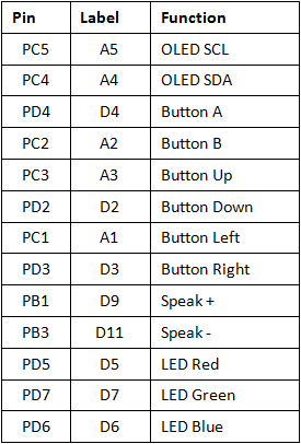
Here is also a table to show what goes where:
I built my Arduboy on some veroboard:

So from the above image you can see how I soldered everything together and added a connector for the battery. Since I don’t have an on/off switch yet, unplugging the battery is the only way to switch it off. One thing to also take care of is where you place the buttons on the right. In my first attempt they were slightly lower, which meant they were obstructing the USB cable needed to program the Nano.
In the future I will probably still 3D print a housing for it, for now I was just focused on getting it to work and writing my first game for it!
Software
Setting up the development environment
Although you can use the Arduino IDE, I prefer something a bit more powerful and would recommend that try out PlatformIO on Visual Studio Code. If you prefer to stick with the Arduino IDE, you can skip to the part where we download the Arduboy library.
Install Visual Studio Code & PlatformIO
Visual Studio Code is a very powerful code editor which you can download and install free from here. Once installed, run it and on the menu bar click View -> Extensions. In the extensions search field type “platformio” and install it.
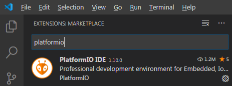
As you can see PlatformIO is an extension that runs on top of Visual Studio Code. It is a great tool for embedded development and also supports the Arduino framework. It provides a more enjoyable programming experience with advanced features like auto code completion and syntax highlighting.
Create a new project
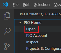
With VS Code and PlatformIO installed you can now create a new project. If you have VS Code running then click the PlatformIO icon (looks like an ants head) in the vertical bar on the left of the window.
![]()
A menu should appear and under “PIO Home” click “Open” which will bring up the PlatformIO welcome screen.
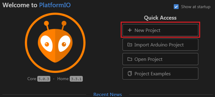
On the right of the welcome screen are some “Quick Access” buttons, select “New Project”.
The Project Wizard window appears where you can give your project a name, maybe something like “MyArduTetris” will do. Next you have to select the board which in this case is the “Arduino Nano ATmega328” and the framework, “Arduino”.
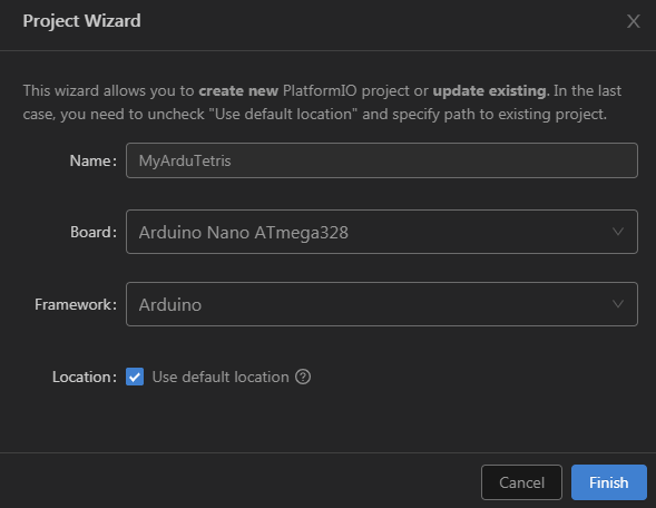
After clicking “Finish” PlatformIO will create a folder under Documents\PlatformIO\Projects where your source code will be stored. The first time you do this it might take a bit longer as PlatformIO downloads all the necessary files and libraries for using Arduino.
When all is done you should see your project folders under the Explorer view on the left side of the screen. Click the “src” folder and inside it you should see “main.cpp” which you can open. It should look very familiar with the typical Arduino setup() and loop() functions.
On the status bar at the bottom you can use the check mark to build the code and the arrow to upload it to your Arduino board.


Download Arduboy Library
Now here you have to be a bit careful. If you use the Arduino IDE to install Arduboy it will install the normal version of the library which runs on the ATMega32u4. This is not what we want, we want the version specific for the ATMega328p. So what you need to do is go to this GitHub page and download it from there.
Lastly extract the downloaded zip file to the “lib” folder in the project you created with PlatformIO earlier. Now everything should be setup and ready for you to start coding.
If you are not using PlatformIO then create a new sketch in the Arduino IDE and extract the zip to the newly created sketch folder.
Arduboy API
Before you start writing your first Arduboy game it would be wise to have a look at the API that they provide. You will find many of the functions you may need already implemented and optimized. In this section we will quickly go over some of these functions and related concepts.
Screen Buffer
Arduboy uses a screen buffer for drawing to the display. This means that when you want to draw something you have to write it to the screen buffer first. Then when you are done call the Display() function which will copy the data from the screen buffer to the actual display.
The display has a resolution of 128 x 64 pixels which gives a total of 8192 pixels. Since the Arduboy display has only 1 bit colour depth, we need 1 bit per pixel. So we have a screen buffer of 8192 / 8 = 1024 bytes in RAM to cover the whole display. As the ATMega328p only has 2kB’s of RAM it eats up half of the available RAM.
Although more elegant functions are available you could also write directly to the screen buffer by writing to Arduboy2::sBuffer. When doing this you have to keep in mind how the screen drawing routine works. It is normally easier just to use the drawPixel() function as it allows you to specify an X and Y coordinate and pixel colour. You can also read from the screen buffer with the getPixel() function, which will return the pixel colour based on the X and Y coordinate that you specify.
Bitmap
Images are normally stored in Bitmaps which are just arrays of unsigned byte values. The first two bytes in the array forms the header which holds the width and height (in pixels) of the bitmap. Bytes following this header hold the actual image data, 8 pixels per byte. Each data byte represents a column of 8 pixels in height where the least significant bit is at the top. So when the bitmap is drawn it will start with the LSB of the first data byte in the top left corner followed by the next 7 bits downwards. Then the next byte is drawn one pixel to the right and again from the top going downwards. This repeats the number of times indicated by the width value after which the next row of 8 pixels high is created.
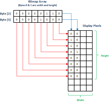
Notice that this way of drawing means that the height will always need to be a multiple of 8 pixels.
Sprites
Arduboy provides some basic sprite operations to make them easy to use. A Sprite is basically just a bitmap which you can easily move around on the screen.
Although you could use functions like drawBitmap() to do the same, the Sprites class provides some very handy masking features. For example you could use the Sprites::drawSelfMasked() function which will only draw the bits set to 1 in your sprite. This gives the effect of having a transparent background. Another handy function is Sprites::drawErase() which will draw bits set to 1 as white pixels and effectively erase the sprite. There are some other handy masks that you could also check out and experiment with.
Another nice feature provided by the Sprites class is that if your bitmap contains multiple images you can cycle through them to create an animation effect.
One thing to be aware of is that the bitmaps that you pass to the sprite functions need to be stored in flash memory space. They do not accept bitmaps in RAM address space.
Frames
The API provides some functions to help manage the frame rate at which your game will run. Two of these functions are setFrameRate() which allows you to set a desired rate and nextFrame() which returns true when the next frame can be drawn. Note that these functions just provides you with a mechanism and will not automatically update the display or do anything else. What happens during the frame time is up to you to decide. Another way of setting the frame rate is by using setFrameDuration() where you can specify the frame time in milliseconds rather than the rate per second.
Buttons
All games need some way to interact with the player so providing support for buttons is really helpful. The API provides various options when it comes to handling the buttons.
If you just want to get the current position of all buttons you can use the buttonsState() function. It returns an unsigned byte where each bit represents the state of one of the buttons. To test a specific button you could also use the pressed() function. I have not used these function a lot but suspect that contact bounce could be something to keep in mind when using them.
Another option which the API provides is through the pollButtons(), justPressed() and justReleased() functions. How this works is that you call pollButtons() at some regular interval (like for example each frame) and then test if a button has been pressed or released during this time with either justPressed() or justReleased(). This has the advantage that due to the time that passes during the call to pollButtons(), the button state settles and mostly eliminates contact bounce.
Sound
Sound is generated by using some of the timer peripheral of the MCU, which means it is basically just a square wave of which we can adjust the frequency. One advantage of this is that it requires very little CPU intervention, allowing sounds and other processing tasks to work in parallel.
The API provides the BeepPin1 class to help with generating sounds. To initialize it you have to call the begin() member function in your setup() somewhere. Once that is done a sound can be generated with the tone() function. It takes a count argument that gets loaded into the timer as well as a duration argument.
To convert the count value to an actual frequency you can use 1000000 / (count + 1). So in other words a count value of 999 will produce a 1kHz tone. The duration value is the length of time that this tone should be played. One catch here is that this time depends on how regularly you call the timer() function of the BeepPin1 class. If you call it each frame then it means the tone will be played for the number of frames specified by the duration value.
Writing Tetris
Everybody knows Tetris, but lets just quickly recap on how the game is played. So you have a rectangular playing field which is longer in height than in width. Shapes called tetriminos, fall from the top of the field at a constant speed which the player can’t control. The player can only move the tetrimino sideways and also rotate it in 90° steps. The goal is for the player to stack the tetriminos in such a way that they form completed rows. When this happens the row(s) are removed and everything on top of the row(s) moves downwards. Should the tetriminos stack reach the top of the playing field the game is lost. To keep the game interesting the speed at which the tetriminos fall are increased as the player manages to destroy more rows. The challenge is to try and remove as many as possible rows without allowing the stack to reach the top.
Just before we look at the source code, keep in mind that this is just my implementation of Tetris and I am sure it can be improved in many ways. The idea was to play and get familiar with the Arduboy library, not to write the most optimized version of the game.
So on to the code. I will just show some snippets here to explain whats going on, the full code can be downloaded here.
Headers
The first thing to do is to include the relevant headers:
#include <Arduino.h>
#include "Arduboy2.h"
#include "bitmaps.h"
Notice that I used quotations in my include as I do not want to use the default location, just in case the normal Arduboy library is installed. Remember this is actually the Slimboy version.
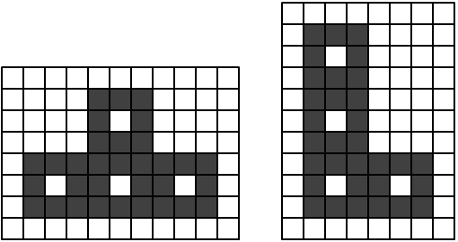
The “bitmaps.h” header defines the actual tetrimino’s and other bitmaps in flash memory. Tetrimino’s are drawn so that they appear to be created out of small 3 x 3 pixel squares. This is then also the height in pixels for each row in the game.
As mentioned earlier, the bitmaps used by sprites should be in flash memory. That means that you can’t read a tetrimino shape to RAM to rotate it and then write it to the screen buffer. For this reason there is 4 versions of each tetrimino, each rotated 90° from the previous. In some cases the same shape could be reused. For example the long I-shaped tetrimino looks the same at 90° and 270° rotation.
Next up some objects needs to be created:
Arduboy2 arduboy;
BeepPin1 beep;
The first one gives us access to the main Arduboy API and the second one adds support for sound. I have read that it has become kind of a tradition among the Arduboy developers to call the Arduboy2 object “arduboy” so I have continued the tradition.
Setup
Now for the setup() function.
void setup()
{
  arduboy.begin();
  beep.begin();
  beep.noTone();
  arduboy.initRandomSeed();
  arduboy.setFrameRate(60);
  RestartGame();
  beep.tone(999, 10);
}
The first line calls arduboy.begin() which initializes the MCU for using the arduboy library. These are things like configuring the pins, initializing the OLED display, etc. Then beep.begin() and beep.noTone() is called to initialize the sound and make sure no sound is being played.
As pseudorandom number generator is used for picking the next tetrimino it needs to be initialize, this is done by arduboy.initRandomSeed(). The way I understand it is that it uses one of the floating ADC channels to read a seed value for the generator.
Next up arduboy.setFrameRate(60) is used to set the desired frame rate that we would like to achieve. Then RestartGame() is called which draws the playing field as well as resetting the game states.
void RestartGame()
{
  arduboy.clear();
  CreatePlayingField();
  DisplayScore();

  // Reset tetrimino position to start from the top centre
  tetY = 0;
  tetX = 63;
  rotate = 0;

  // Select random tetrimino
  p = random(0, 7);
  p *= 4;

  // Reset score
  score = 0;
  level = 0;
}
RestartGame() clears the screen and then starts drawing the playing field with a call to CreatePlayingField(). This function first tiles the screen with a background bitmap, followed by creating a black filled rectangle more or less in the middle of the screen. Then lines are drawn to the left, right and bottom of the rectangle to create the border of the playing field. Next DisplayScore() is called which just writes the “Lines” and “Level” labels to the left and right of the playing field as well as the values of the score and level variables.
The last function in setup() just plays a short beep sound to indicate the start of the game.
Main Loop
Moving on to the main loop.
void loop()
{
  // Wait until ready for the next frame
  while(!arduboy.nextFrame())

  frames = arduboy.frameCount;
  arduboy.pollButtons();
  beep.timer();

  if ((frames - framesPrev) > (10U - level))
  {
    // Remove sprite at previous position. This allows the collision detection
    // to only look at the playing field.
    Sprites::drawErase(tetX, tetY, tetriminos[p + rotatePrev], 0);

    if (!Collision())
    { // No collision

      // Check for collision if X axis movement is applied
      if (moveX != 0)
      {
        // Apply any x movement that has been requested
        tetX += moveX;

        // If move would result in a collision then undo it
        if (Collision())
          tetX -= moveX;

        // Clear move requested
        moveX = 0;
      }

      // Check for collision if rotation movement is applied
      if (moveR != 0)
      {
        rotate += moveR;
        if (rotate > 3)
          rotate = 0;

        if (Collision())
          rotate -= moveR;

        if (rotate > 3)
          rotate = 3;

        moveR = 0;
      }

      // Increase y to move tetrimino down
      tetY++;
    }
    else
    { // Collision

      // Redraw the sprite so that it becomes part of the playing field
      Sprites::drawSelfMasked(tetX, tetY, tetriminos[p + rotatePrev], 0);

      // Check if game over
      if (tetY == 0)
        GameOver();

      // Reset tetrimino position to start from the top centre
      tetY = 0;
      tetX = 63;
      rotate = 0;

      // Load the next tetrimino
      p = random(0, 7);
      p *= 4;

      // Check if a completed row has been formed and remove it
      RowComplete();
    }

    // Draw sprite on new position
    Sprites::drawSelfMasked(tetX, tetY, tetriminos[p + rotate], 0);

    framesPrev = frames;
    rotatePrev = rotate;
  }

  // Test for button pressed
  if (arduboy.justPressed(A_BUTTON))
    moveR = 1;                              // Request to rotate to the right in the next frame

  if (arduboy.justPressed(RIGHT_BUTTON))
    moveX = 3;                              // Request to move to the right in the next frame

  if (arduboy.justPressed(LEFT_BUTTON))
    moveX = -3;                             // Request to move to the left in the next frame

  arduboy.display();
}
The loop starts of by waiting until the next frame can be displayed. In setup we aimed for 60 frames per second so the loop should pass this point roughly every 1 / 60 = 16ms. The rest of the time the CPU would just be running in a loop, which is not the best use of it’s time but for this basic Tetris it’s okay.
When it is ready to process the next frame it starts by making a copy of the current frame count and update the buttons and software timer used for sound.
What I have done next is to update the game states every 10th frame. This means that the tetrimino will drop one pixel every 10 frames when the game level is 0. As the player advances through the levels, updates will happen more often causing the tetrimino to drop faster.
When an update occurs the sprite at the previous position is removed since we would like to redraw it one position lower on the y axis. The removal of the sprite also makes sure that it does not interfere with the collision detection. A collision check is then performed to check if the sprite would collide with anything if it moved one pixel down on the y axis. If no collision is detected then it applies any x axis movement requested by the player and repeats the collision check. In this case if the player tried to move outside of the bounds of the playing field a collision with the playing field border would be detected. If so then the player’s request is undone preventing the sprite from moving in the requested x axis direction. This same technique is then used to detect if any rotation from the player would cause a collision and if so it is undone. At the end of these checks, if there was no collision the sprite is redrawn at the new y axis position.
Now what if there was a collision while the sprite move downwards. In this case the sprite is redrawn at it’s previous position so that it becomes part of the playing field. Then a quick check is performed to see if the y axis reached the top to signal that the game has been lost. If not then the x, y and rotation variables are reset for the next sprite and the bitmap for this sprite randomly selected. Finally a check is performed to search for any completed rows and if found they are removed and the score updated.
Collision detection
The collision detection function compares the pixels of the sprite with the pixel of the sprite’s location in the screen buffer. It actually uses the screen buffer pixels one row lower than the sprite position so that it detects if the next downwards position will collide rather than the current position.
As collisions only need to be checked below the sprite, only the lower bytes of the sprite is considered. So in other words if the sprite has a height of 16 pixels then only the lower 8 pixels are used for collision checking.
Checking for completed rows
After a collision has been detected on a downwards movement another check is run to see if any rows where completed. The tetrimino blocks consist out of little square boxes which means that if you have a complete row of white pixels then you also completed a row of tetriminos.
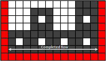
So this check is actually very simple and starts at the bottom from one side of the playing field counting white pixels (black in the above image) until it reaches the other side of the playing field. If the number of pixels matches the width of the playing field then you have a complete row. If a row is completed then it is removed by copying all pixels above it 3 lines down. If the row is not completed then move 3 lines up to check the next row until reaching the top of the playing field.
This should give you a pretty good idea of how the game code works. I have also added a fair amount of comments to the code which you can look at for more details.
Conclusion
Well I have to say that I wish I started playing with Arduboy earlier. As I discovered it is much more than just a Leonardo with a screen and buttons. I overlooked things like the battery and charger circuit on the hardware side and then there is the really nice Arduboy library on the software side. The library really helps to make simple game programming accessible to everyone. It’s actually incredible to see what games people have written for Arduboy!
There is also a very active community behind Arduboy which can help a lot when you get stuck. They even have their own magazine!
Well, hope you found the Arduboy as exciting as I did and could also learn something new!