
Part 1 can be found here.
My aim for this project was to fit the largest screen possible that I would consider portable. Just based on availability and the screen sizes of cellphones I decided that 5″ was the size to aim for. For reasons I cannot remember this did not happen and I settled with a 3.5″ screen from eBay driven over SPI, closely resembling this one from Waveshare.
3.5″ SPI screen
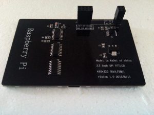 The 3.5″ screen from eBay is driven by SPI. Finding documentation for the screen proved to be more difficult than anticipated but I gathered it closely resembles a 3.5″ Waveshare screen for which drivers are available.
The screen itself has a resolution of 320×480 and provides a resistive touch interface which I did not intend to use. It also comes ready to be used as a LCD shield for a Raspberry Pi 1/2/3. As I am using a Pi Zero and wanted more flexibility for packaging reasons and replaced the shield connectors with wires connected to the Pi.
I found instructions for the Waveshare screen here and after some tinkering got it to work… well partially. While the Raspberry Pi boot sequence and the Retropie splash screen are rendered perfectly, the screen turns blank soon afterwards. I suspect I only need to change a few settings to get everything going but were unable to do so. While trying to debug this problem I decided that using a SPI driven screen for a game console is not ideal. I learned that the bandwidth limitation of SPI on the Raspberry will influence the gameplay. From the Raspberry Pi forums:
The issue with these small "plug in on top" screens is that they have to communicate via the SPI interface, which limits their update rate. Consider:
320x480x3 = 460,800 bytes for one frame (24 bit color needs three bytes)

That is 13,824,000 bytes per second at 30fps. Which is 110,592,000 bits per second, with 0 overhead

Which is considerably more than the 25Mbps - 36Mbps that I have seen reported for maximum SPI data rate on the Raspberry Pi.
Instead of continuing debugging the SPI screen I decided to switch to a composite driven LCD screen. The other easy choice is a small HDMI connected monitor. I will reuse the 3.5″ SPI screen for a different project somewhere in the future and will put it away for now thanking it for what it taught me:
- research the suitability of your components for their intended use
- there is a reason things are cheap on eBay, no documentation or support and lower quality. Just buy from Adafruit or official Raspberry Pi stores if you want something that will work from the start. You will save yourself some time and probably some money in the long run as well.
3.5″ Composite screen

Apart from the HDMI output, the Raspberry Pi also provides a composite AV out. On the RP1 this is done through the headphone jack, something I have never used, but on the Zero two solder points are provided. Like many other I bought a small LCD display for a car reversing camera and repurposed it for my project.
First the LCD and controller board are removed from the enclosure. For automotive use the LCD needs a 12V supply to operate. Most of these reversing camera displays are however copies of each other made in China and like other projects the one I bought makes use of the XL1509 DC-DC converter to chop the 12V supply to 5V for the rest of the circuitry. I desoldered this chip and connected my 5V supply to the board where the chip’s 5V output pin was. Now my screen and Raspberry Pi is powered from the same 5V supply. After soldering the composite inputs to the Raspberry Pi Zero I powered everything and everything worked on the first try.

Next
Next I will look at the options for an enclosure or adding user input buttons and switches.
One thought on “RetroPie Arcade Part 2 – The screen”