
In recent years the FPV (First Person View) drone racing industry has grown tremendously with tournaments around the world offering up to one million dollars to the fastest pilot!
The widespread interest has flooded the market with low cost components that is of decent quality, making it easier and cheaper than ever to get your hands on one of these incredible little machines. Depending on how confident you feel you can either source all the components yourself (or get a kit) and build one or just buy a RTF (Ready To Fly) model. Personally, I prefer the first option and like the idea of better understanding the different components and how they interact. The other advantage is that it would be easier to repair (crashing is inevitable ;-). So in this post I will talk you through my build of a Martian 3 220, also explaining a bit how and why I chose the components.
The Frame
Browsing some online shops to find a FPV frame, one soon gets overwhelmed by the many options available. There are larger frames, smaller frames, frames cut from a single piece of carbon fiber and others made from individual parts. Then there are true X frames, H frames, stretched X and many others, how can one choose a frame!?
I wanted something compact but not so small that installing the electronics would require me to work under a microscope with tweezers. The frame should also have enough space to allow me to add an action camera for making some HD videos. Keeping the frame on the medium to small side (at least for racing drones) also meant I could get away with smaller and thus lower cost motors and speed controllers. These parts could then be upgraded later if I outgrew them, or more probably after destroying them in a crash. Choosing a frame made from individual parts also seemed like the more logical option since a broken arm could easily be repaired in a few minutes. Single construction or uni-body frames are lighter since they do not require extra screws and parts to attach the different sections, but would require a complete rebuild after a serious crash.
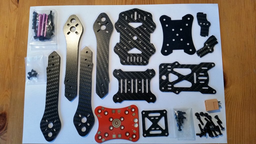
So taking these points into consideration I finally went for the Martian 3 220 frame. At around 20 Euro the price was inline with what I budgeted for a frame. It is considered a medium size frame, measuring 220mm from motor to motor.
The frame consisted of the following individual parts:
Motors
The next big question is which motors to use on this frame? To find an answer for that I had a look at what propellers would fit this frame. From the manufacturer specifications I could run up to 5 inch propellers. So I knew that to use the frame to it’s full potential I would need motors that could at least turn 5 inch propellers without burning. So I had a look at the specification sheets of a couple of motors. Typically they provide the maximum thrust, current draw and power for different propeller sizes, it normally looks something like this:
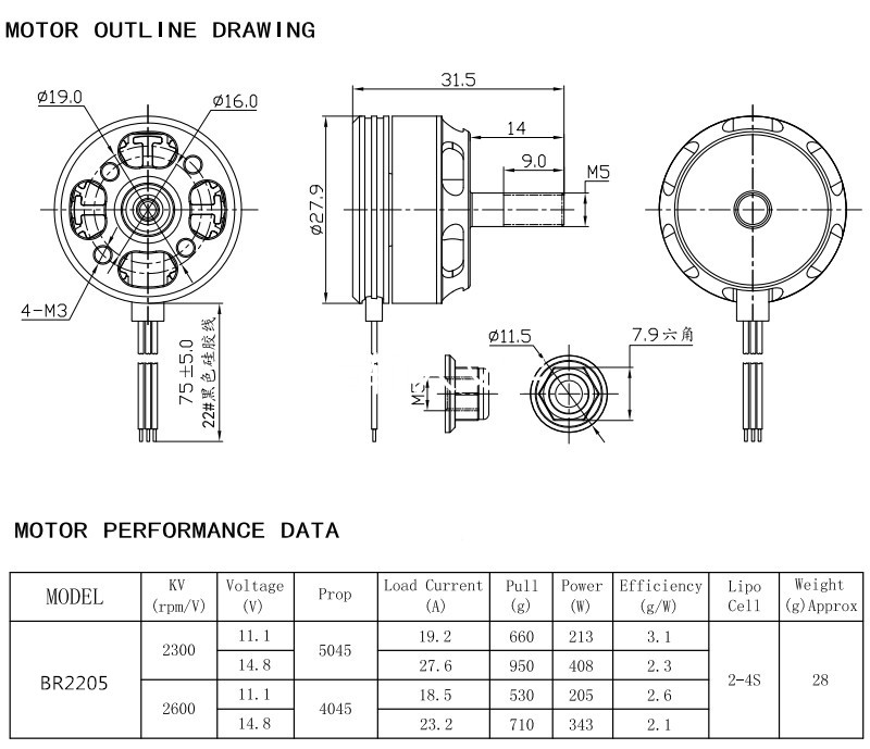
I found the Racestar BR2205 2300kV motors (with the above specs) which seemed like good candidates for the job. Running 5 inch props at maximum should provide 950g of thrust! The idea is off-course not to run them at max very often, I was thinking more to design around 75% of the maximum. That would give about 712g of thrust multiply that by 4 motors and the total thrust would be around 2848g. If the drone (with some action camera) would be around 900g, that would give a power to weight ratio of just over 3:1 which is fine for average flying.
Problem was that these seemed to be very popular motors and I could not find them in stock at the local online shops.
Instead I found the Chaos FPV 2205 2300kV motors from UnmannedTech in the UK which looked very similar at only 25 Pounds for a set of 4. They claimed that these motors come from the same factory as the Racestar motors and have even better performance. I took their word for it and bought 4 motors, two with clockwise thread and two with counter clockwise thread on the output shaft:
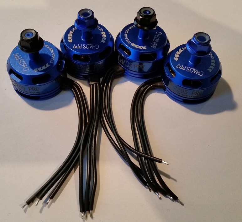
By the way, if you are new to brushless dc motors, the kV rating on the motors specifies RPM per volt. So in the case of the above motors they will do 2300 RPM for each volt that is applied, BUT this is under no load conditions. The moment you add a propeller this number drops significantly, but it still gives you a good idea. The “BR2205” part of the motor model name typically reveals some information about the size of the stator of the motor (in this case 22mm wide and 5mm high). The stator is the part that is not moving and have the wire windings. Without going into the details, the size of the stator in-turn gives you an idea of the power that the motor can provide.
Propellers
Since my motors and frame can support up to 5 inch propellers (bigger and it would hit the middle section) I decided to go all out and use 5 inch props. The next question is 2 blades or 3 blades. Typically a 3 bladed prop provides more thrust than the same size 2 bladed prop. This higher thrust comes at the expense of higher current draw and lower efficiency. I plan to use a decent battery and prefer the extra power to efficiency so decided on the 3 blade props.
Speed controllers
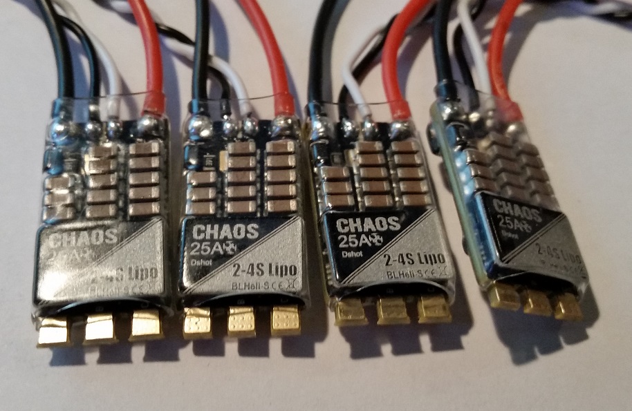
When choosing the Electronic Speed Controllers (ESC’s) for my new drone, the biggest question was what current rating do I use? Lower rated controllers are cheaper but might overheat and burn out if the motors asks for more than they can deliver. Choosing higher rated controller would obviously be safer but they will be a bit heavier and also more expensive. The motor specifications indicated that at maximum power, the motors could draw up to 27.6A! The thing is unless you are a professional racer, I doubt you would hit full power very often and when you do it would be short bursts. My guess is that the drone would hover somewhere between 30% and 40% of the full power rating (assuming it weighs about 900g). Most of the flying would most likely happen between 40% and 60% giving 27.6A x 0.6 = 16.56A, so a 20A ESC should be sufficient. Just to make sure I also Googled around the internet and found a couple of people reporting that 20A controllers ran fine on their 220 class drones with similar (Racestar) motors and 5 inch props. These ratings are for continuous current and often these ESC can handle burst currents more than double the rated continuous current. UnmannedTech stocked 25A controllers carrying the same Chaos name as their motors and runs the popular BLHeli_S firmware. Another nice touch was that these controllers actually supports D-Shot which means the flight controller can use the newer digital protocol to command them. At 23 Pounds for a set of 4 I also added them to my order:
Flight controller
Selecting the flight controller was probably the most exciting part. Coming from the world of ArduPilot I had no idea of the controller boards available for FPV drones and a new world opened up for me! There are again many flavours to choose from, all with their own special features and claims why they are better than the rest. Then there is also a selection of firmware that runs on these boards. When you first step into this realm it can be again a bit intimidating and not so easy to make a choice.
Starting with the firmware I followed the advice of some YouTube bloggers and settled on BetaFlight. It seems like the most up to date flight control software with a large following and finding help online would not be to hard.
On the hardware side it seems like the ST Microelectronics chips are dominating this market when it comes to processors/microcontrollers. The flight control boards are referred to as F2, F3, F4 and F7 which are all different versions of STM32F microcontrollers. The IMU sensors on the board includes mostly gyro’s and accelerometers in the form of MPU6000 or ICM series chips. Some boards also include a barometer to help with altitude stability. Since these boards are designed for racing, and waypoint flights are not part of the FPV scene, a compass and GPS is not used very often. Some other additional hardware included with many boards are on-board regulators and OSD chips. Small switching regulators built onto the boards help to keep things neat and tidy as you don’t need to mount a separate regulator board and wire it up. OSD is used for On Screen Display of telemetry when using a camera and is also included on many boards.
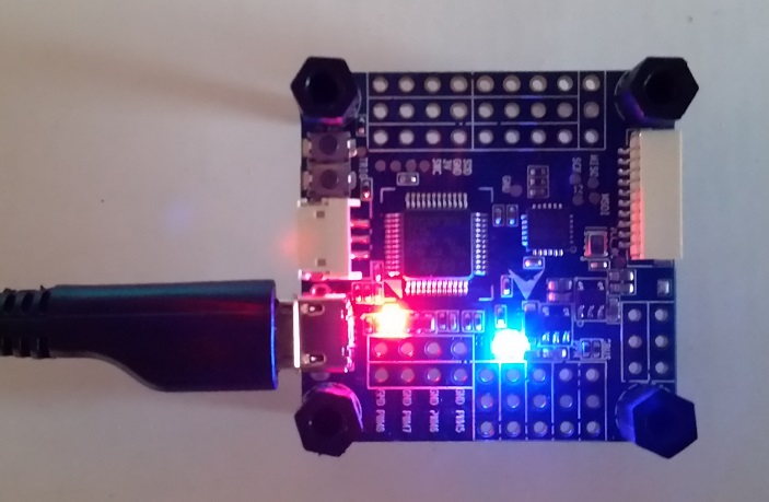
I settled for the OmniBus F3 board using the MPU6000 IMU, it has on-board voltage regulation and OSD chip as well as a barometer. This is an older board and thus not too expensive which seemed like a good start for me, I paid 21 Pounds for it:
Battery
These type of racer drones typically use either 3S or 4S Lithium Polymer batteries. The “S” part refers to the number of cells wired in series inside the battery pack. Each of these cells have a nominal voltage of 3.7V, but when fully charged they are 4.2V each. So using a 3S battery would give you 3 x 4.2V = 12.6V when fully charged. Typically a higher voltage battery allow your motors to spin faster (remember the kV rating we talked about earlier). I already decided to go with the biggest props I could fit on this drone. Therefore I strayed towards a bigger battery and opted for the 4S. One thing to keep in mind is that you need a special charger to charge Lithium Polymer batteries and if you are going to buy a battery make sure you also look for a charger.
Radio
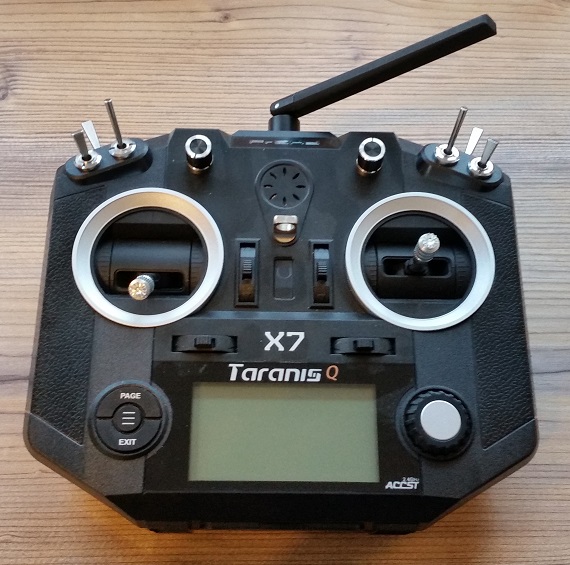
A crucial part of any RC model is obviously the radio, there is no flying without it. Here also one can choose from a wide variety of options and some very capable radios can be had for not much. I tried to find a compromise between price, quality and features and in the end went for the FrSky Taranis QX7. Like most modern radios it operates on 2.4GHz and uses a proprietary spread spectrum technology called ACCST (Advanced Continuous Channel Shifting Technology) to ensure a robust link with your drone in this busy band. The radio provides 6 switches and 2 turning knobs in addition to the gimbals which can be mapped to the 16 channels it supports. Another nice feature is that it runs OpenTX which is an open source firmware with a large active community behind it:
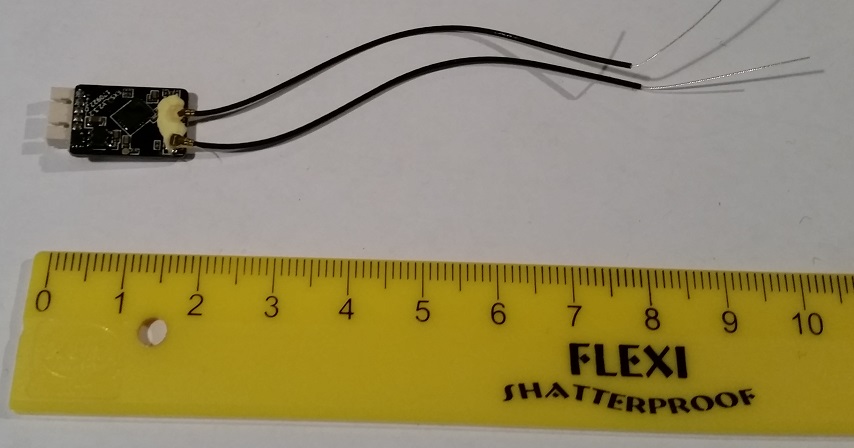
It supports a good selection of receivers to suite most types of drones and I have found them to be very reasonably priced. For this racer I went with the R-XSR receiver which at only 16mm x 11mm is incredibly small and perfect for the limited mounting space. I paid 15 Pounds for the receiver:
FPV Gear
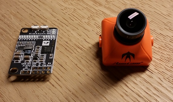
Since this is a FPV racer, it needs a FPV setup. For this I bought a Runcam Swift 2 camera with Matek 40CH 5.8GHz video transmitter. On the ground side I got the Eachine EV800D box type goggles.
Tools and sundries
Some of the tools and extra parts I used for building the racer include:
- Soldering iron and solder
- Side-cutters
- Wire-strippers
- Small pliers
- Small 5.5mm hex nut driver
- Silicone insulated stranded wire
- Heat-shrink tube
- Cable ties
Building the Racer
So onto the fun part! I started by first building the lower part of the frame, working my way up to the point where the arms and power distribution board were fixed. With the arms in place, I could loosely place the speed controllers and motors on the frame and start trimming the wires to the correct length. After trimming the wires I removed the ESC’s and motors, soldered them together and then re-installed them again, a bit more secure this time. I also soldered the ESC’s power wires to the distribution board. For fixing the ESC’s to the arms I used some clear heat-shrink tube.
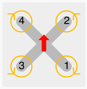
Next up was the flight controller, first I soldered short wires from the power pads on the distribution board to the power input on the flight controller (since it has a builtin regulator). Then I soldered the signal and ground wires from the ESC’s to the correct output channels, it’s important to get the order correct and should be like this:
With the ESC’s connected I continued with the soldering the receiver wires to the flight controller board. I had a rough idea where I wanted to place the receiver so I also slightly trimmed the wires before soldering. Generally one should place the receiver in such a position that the antennas would be visible from most angles and that they also do not move in the way of the props.
With the critical electronics installed I completed the rest of the frame and mounted the receiver on the top plate.


At this stage I did not yet install the camera and video transmitter and thought it better to first perform some test flights.
Configuration
I previously downloaded and installed BetaFlight Configurator, which is the tool you need to flash the firmware to the flight controller board and also to configure the parameters. Using this tool I performed all the calibration processes and also used the motor test feature to make sure that the correct motors spin in the correct directions. If they don’t you would need to swap any two wires between the ESC and motor or change the direction in the ESC firmware. If you have them in the wrong position you could either re-solder the ESC to the correct channel or remap it using the Configurator tool.
Something to note is that since I am using the DShot protocol, ESC calibration is not required. Another important thing to check is that the radio channels works properly and that the flight modes are configured and working as expected. This normally also requires one to perform some configuration on the radio side, like mapping the switches to the correct channels. I used one of the 3 position switches to select between ANGLE mode with BARO assistance, HORIZON mode and ACRO mode. This is pretty much also the order in how much the flight controller will assist. In the first mode the flight controller will use the accelerometers to self level the drone and the barometer to help keep the altitude. The second mode removes barometer support and allow larger pitch and roll angles. The last mode is ACRO and provides mostly just gyro support, this is the most difficult mode to fly but also allows for the most acrobatic manoeuvres. For arming the drone I used a 2 position switch on the opposite side of the radio.
After looking through all the parameters and making sure they are correct and saved, the drone was ready to have it’s props and battery fitted for the first test flight.
First flight
After double checking everything and making sure all batteries are fully charged I took the drone to a nice open spot on the lawn for a first flight. Flipping the ARM switch the motors spooled up nicely and while in ANGLE mode I gently increased the throttle. She lifted off smoothly and kept a pretty stable hover position (considering there is no GPS correction).
Gently flicking the throttle I could feel the urgent response and the promise that it had a lot more to offer in terms of power. It would take me a decent amount of flying time before I would be able to fully use the power of this little racer!
Final thoughts
In the end building the racer costed me around 200 Pounds, excluding the radio since I already had it, which I think is not bad for trying out this hobby and ending up with a pretty neat little drone. It is also possible to build it for a bit less if you opt for maybe an older flight controller, smaller battery, lower cost camera, etc. If you are completely new to model aircraft I would recommend to first get a radio and spend some time on a simulator like Liftoff. It would give you the confidence to make that first flight after building your drone and most likely save you a couple of crashes.
Building a drone like this is very rewarding which is even further accelerated on that first take-off and seeing it fly! I hope you found this post interesting and that it gave you some inspiration to also build one of these incredible machines!