
In today’s post I want to share some of my findings after playing a bit with garage door openers and wireless sensors operating in the 433MHz radio band. These kind of remotes are sometimes also referred to as fixed code remotes because the messages they send are fixed, but more on that later. The goal was to learn how these devices work and ultimately integrate them into my own projects. This would then allow me to use these and many other off the shelve devices like these in my future projects. As the title suggests I used Arduino hardware and libraries but it could be easily ported to other platforms as well.
Radio hardware
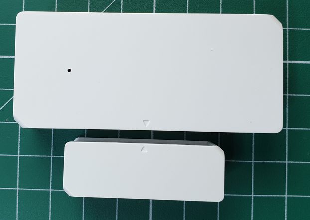
For this experiment I bought a cheap 4 button remote and a Sonoff DW2 door sensor from Ebay. These two devices are fairly often used in DIY home automation projects and will be my test transmitters. I also had a pair of the very cheap FS1000A transmitter and MX-RM-5V receiver modules laying around. They came as a pair but I was actually only after the receiver module.


Looking at the spectrum
After receiving the remote and door sensor I wanted to confirm that they both do indeed operate in the 434MHz band. So I fired up the spectrum analyzer (Signal Hound BB60) and got the spectrum plots below.


So here we can see that both signals are very close to 434MHz. The remote sits a little above it at 434.02MHz while the door sensor sits slightly below at 434.92MHz. In Europe we use the ETSI EN 300 220 standard for devices operating in this radio band. According to the standard these devices are allowed to operate from 433.040MHz to 434.790MHz. They also need to keep their transmit power below 10mW and occupied bandwidth below 25kHz. So looking only at the frequency both these devices seems to be okay.
It is interesting to note that the signal from the door sensor looks a bit narrower than that of the 4 button remote’s signal. Most likely it has some better filtering to allow it to comply with regulations. It is after all from a well known brand and it indicates that it conforms to the regulation with it’s “CE” marking. On the other hand the 4 button remote was real cheap and has no “CE” marking on it. That being said, I used the spectrum analyzer to measure its occupied bandwidth (99% of mean power) and got 22.6kHz so it seems to comply.
Signal over time
Switching the spectrum analyzer to zero span mode I can view the signal over time. After tuning the parameters a bit I could get the traces below.


Now I already had a strong suspicion that these devices will use OOK (On Off Keying) which is a type of ASK (Amplitude Shift Keying) modulation and these traces confirmed it. This basically just means that the transmitter generates a constant carrier signal which is switched on or off to relay the data. We can clearly see this in the traces above. OOK is mostly used on these devices as it is really simple and cheap to build transmitters and receivers circuits for it.
Another interesting observation is that when I press the button the signal is sent multiple times. It’s not so clear from the above traces but it could easily send the same frame 3 to 4 times. I guess this is to give the receiver more than one chance to catch the signal in case it was not ready or interfered with the first time.
Decoding the signal
So now that we can see the bits being transmitted how do we decode it? There are many different protocols used for these applications but one of the more popular ones is known as EV1527. This protocol starts with a short high pulse of 1 time period followed by 31 low time periods which forms the preamble part of the frame. The purpose of the preamble is to let the receiver know that this message is not just some noise but actually intended for it. Following the preamble we get a 20 bit unique identifier of the device and 4 bits of actual data which the remote wants to share. In the case of the remote the data would be which button was pressed. The identifier and data bits are encoded so that a low (0) bit is represented by a high pulse of 1 time period followed by 3 low time periods. A high (1) bit is just the opposite with a high pulse of 3 time periods followed by 1 low period. The time period can vary between devices but is typically in the range of about 300us to 500us. Although I have tested another device which went down to 280us or even lower.

But how did I know that my devices used EV1527? Well I looked at the expected preamble which should be a pulse of some time period followed by no pulses for another 31 time periods. Using the marker tool on the zero span traces, I measured the period of the short pulses and got about 308us. Then I measured the period where there was no pulses for a long time and got about 9.57ms. This means after the short 308us high period I received 9.57 / 0.308 = 31.07 low periods, which matches the EV1527 preamble. Additionally I also counted the bits after the preamble which added up to 24 (20 identifier + 4 data) and this also matches with the expected number of bits used by the protocol.
Knowing the protocol, lets try to decode the remote control signal. The first thing would be to look for the preamble, in this case a short high pulse followed by a very long low period. From there we count 24 more high pulses and that should give us the transmitted frame.

From here it’s actually very easy, a short pulse would be a 0 bit and a longer pulse would be a 1 bit. Using this information we get 001110000110011000001000 which is 3696136 in decimal. Since the first 20 bits is the identifier the identifier would be 00111000011001100000 which is 231008 in decimal. The last 4 bits is the data which gives 1000 in binary or 8 in decimal.
Arduino and RCSwitch
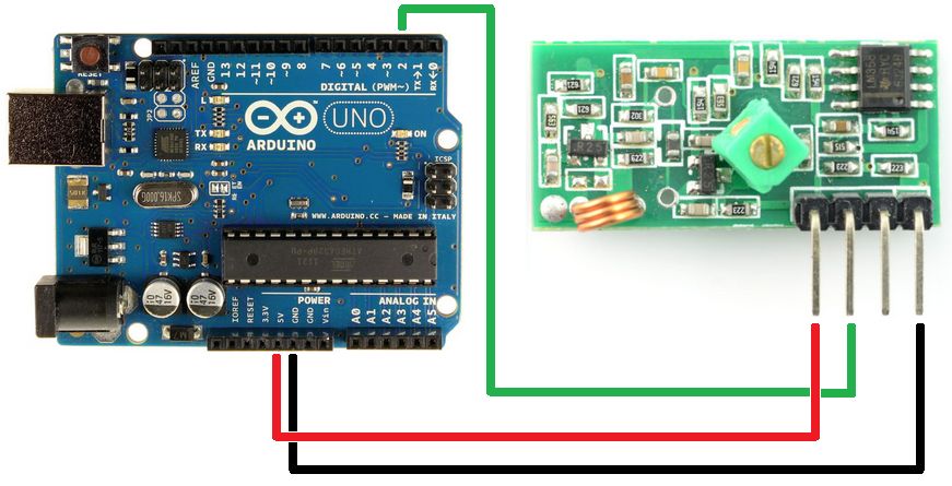
Now that we understand how these devices work how can we incorporate them into our own projects. If you are using Arduino then the easiest way would probably be with the RCSwitch library and a basic OOK receiver module. The receiver module I used was the MX-RM-5V I mentioned at the beginning. Connecting it to an Arduino UNO board is pretty straight forward with 5V and GND on the UNO going to 5V and GND on the module. The DATA pin on the module then goes to pin 2 on the UNO.
To try it out install the RCSwitch library and load the “ReceiveDemo_Advanced” example sketch that comes with the library. Then upload the example sketch and open up the serial monitor. If you now press one of the buttons on your remote some details will be printed to the terminal. Below is an example of the output:

I used the same button as I did when we looked at the signal in zero span mode. So now we can easily compare the output and it’s a perfect match! Both our hand calculated and the output from RCSwitch gives a code value of 3696136. It also very accurately matches the pulse period we measured at 308us. If we look at the raw data we see the duration of each period. The first value is the low period of the preamble followed by the identifier and data. Also interesting to note is that although the pulse length is 308us we have periods as low as 92us! This is not the norm but just shows that our decoding algorithm should allow some tolerance margins.
Using the RCSwitch library we can now easily create projects using these fixed code remotes and sensors.
Security & Rolling Codes
As we saw in the above experiments it’s pretty easy to read and decode these fixed code garage door openers and sensors. Since the code always stays fixed our receiver can just listen for it and then act on it. This is great for us hobbyists as it allows us to easily incorporate these devices into our projects. But not so great is we rely on these devices to keep our cars safe in our garage! A would-be burglar could record your code when you arrive at home and later that night replay it to open your garage door again.
One solution to this problem is to use what is known as rolling codes as opposed to the fixed code system we looked at up to now. There are different ways these systems are realized but it basically works by sending a new code every time. The receiver will then not accept a code which it has previously received. So if our burglar would replay an old code it would be ignored by the receiver. This is a nice solution but creates some new challenges. For example how does the receiver know what the next valid code would be? Simply increasing the code value would not be a very secure solution. The burglar could also just increase the recorded code to create a new valid code.
One way to solve this is through a pseudorandom number generator function on both devices. Then provide the transmitter and receiver with the same seeding value. This basically means that both transmitter and receiver will generate the same “random” numbers. So when you pair a transmitter and receiver they have to share the seed value.
Another approach is to just simply increase some value in the code and then AES encrypt it. The encrypted code will look completely different even if just a single bit changed. This makes it almost impossible for our would-be burglar to decode, increment and send it again. Unless of course he gets the encryption key!
But what happens if you press the remote button by accident or while not in range of the receiver? The transmitter and receiver would then be out of sync. One solution is for the receiver to also accept some future codes.
Anyway, I am getting side tracked here. The idea was just to briefly address the security aspect of fixed codes and present rolling codes. I find this a very interesting topic and would also like to learn more.
In the end
Well as always, I hope you found this post interesting and helpful for future projects!