
In this post I want to talk a bit about the use of accelerometer and gyroscope sensors to perform attitude (roll, pitch and yaw) estimations. Systems that perform these kind of tasks are often referred to as AHRS (Attitude and Heading Reference System) and is commonly used where it is important to know the attitude and heading of an object. Some of the best examples for me are probably in the use of autopilot or flight stabilization controllers. But the applications for such systems are not limited to flight and can also be used on land, like for example in balancing robots, head tracking in virtual reality headsets or special video game controllers.
We will start by quickly looking at the basics of gyroscope and accelerometer sensors and how each one can be used to estimate tilt. Then we will get more practical and use a sensor breakout board together with an Arduino Uno to put the theory to the test. The sensor that we will be using is the popular MPU6050 which has both a 3-axis gyroscope and a 3-axis accelerometer on the same chip. These kind of chips are often referred to as an IMU (Inertia Measurement Unit) sensor and many times also includes a magnetometer (compass), like for the MPU9250. The term Degrees of Freedom (DoF) is also widely used to indicate the number of directions an IMU sensor can measure. The MPU6050 has 6 DoF consisting of 3 accelerometer and 3 gyroscope axes, if we added a 3 axis magnetometer (compass) we would have 9 DoF (this is the case for the MPU9250).
So let’s start by looking at these two types of sensors and the theory behind how they could be used.
Gyroscopes
A gyroscope or just gyro in short is a type of sensor that measures angular velocity, or in other words how fast the sensor is turning around a certain axis (X,Y or Z). It therefore also makes sense that the output from a gyro is measured in degrees per second (°/sec) or sometimes also abbreviated to “dps”. One of the key things to always keep in mind is that a gyro measures velocity (speed) so if the sensor is not moving (turning around some axis) it will output a low value. In a perfect world a gyro at rest should output 0°/sec. and a gyro turning at a constant speed would output a constant degrees per second value.
So how can we use angular velocity to determine tilt? Well if we rotate an object around an axis at 5 degrees per second for 2 seconds then that object would be 10° rotated or tilted from it’s initial position. Or another example, if you rotated it at the same rate for 2 seconds in one direction and then another 2 seconds in the opposite direction then it would be 0° rotated. As you might have noticed, what we are doing here is to integrate the angular velocity around an axis over time and this gives us the tilt around that axis.
In the plot below I have rotated the sensor about 45° and then kept it in that position:
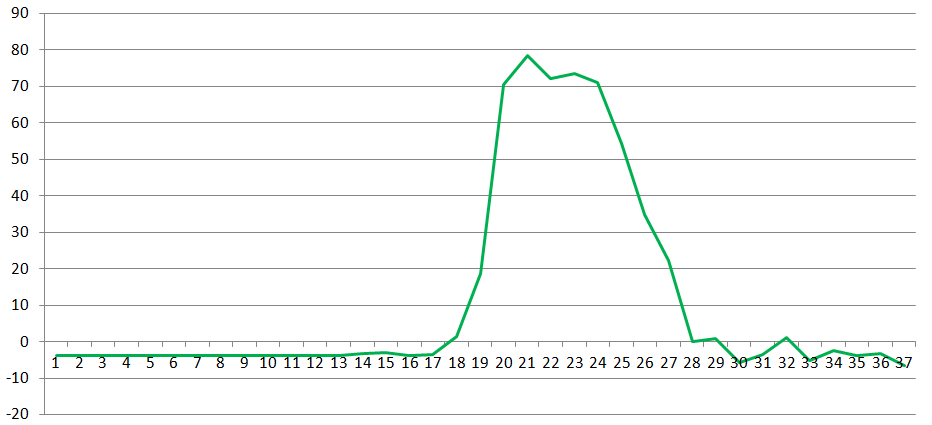
What we see is an increase in the velocity as I start to rotate it and then as it gets closer to the desired angle the change in velocity decrease again. The end result is this peak that we see, but remember that although the reading went back to almost 0 again the sensor was still rotated at about 45°.
Like we mentioned, to estimate the tilt we need to integrate the output of the sensor. To do that we would need to break the output up into discrete samples over time. In the above plot the sensor values was read every 100ms (giving a sample rate of 10Hz) so this would be the time we need to use for each sample. All that is left to do now is to sum the product between each sensor reading and sample time. In other words, take the first sample multiply it with the sample time then add that to the second sample multiplied with the sample time and continue like that. If you kept your time units in seconds and the angular units in degrees then the result would be the tilt in degrees. So let’s do this with the plot, the table below gives the readings from sample 17 to 28 (the rest of samples has a negligible influence on the result):

Seems like my aim was a bit off and I actually rotated it just over 49°.
Something to note is that in this example we sampled at 10Hz which may or may not be enough for your project. By sampling faster we can improve the accuracy of the estimated tilt since the discrete blocks would more closely represent the actual rotation.
Accelerometers
As the name of these sensors suggests, they measure acceleration in a certain direction and provide an output in meters per second per second (m/s/s) in a given direction. When a car stands still it has an acceleration of 0 m/s/s and when that same car drives at a constant speed of 60km/h it still has an acceleration of 0 m/s/s. The acceleration will only change when the car starts moving or starts slowing down if it was previously moving.
How can we then use accelerometers to determine tilt? The answer lies in a force that we are all familiar with, gravity, which as we know pulls everything on earth towards it at a known rate of about 9.8m/s/s or 1g (“g” is used to denote the acceleration force of gravity). If we have a sensor which can tell us the acceleration that it is experiencing in a given direction and point it towards earth it would read 1g. Pointing this sensor perpendicular to the earth it would give us 0g.
So as we can see, by monitoring the effect of gravity on our sensor we can estimate the tilt of the sensor.
In the graph below I have rotated an accelerometer around it’s x-axis and plotted the result:

The response we see here closely resembles that of a sine function, so this means that by taking the inverse sine of the accelerometer output we can estimate the tilt. The sensor started in a horizontal position and read close to 0g, the inverse sine of 0 matches with our expected tilt of 0°. As the sensor started to rotate the output decreased until it reached a minimum of -1g and was positioned vertically, again the inverse sine of -1 matches with our expected tilt of -90°. Then continuing the rotation, the output increased back to 0 as it reached the horizontal position again. The same happens for the second half of the rotation with only the values inverted.
This is pretty handy but we still have a problem, if the sensor outputs 0.2g we can calculate the tilt but we don’t know in which direction (forward or backwards) it is tilted. A second problem is that if you look closely at the previous plot you will notice that the same change in the accelerometer values will not always provide the same change in tilt. When the sensor is close to alignment with gravity (points 9 and 21) the changes in acceleration provides smaller tilt angles than changes when the sensor is perpendicular to gravity (points 1 and 15). This means the response of the tilt output is not completely linear. To solve this we need to add another axis to our calculations. If this axis is following or leading the direction of tilt by 90° then we would have a much more linear response. This can be even further improved by adding a third axis which then provides us with a linear response. I will skip the math of how the final formula is derived for now, and just provide the formulas that we can use to obtain roll and pitch:

Using the MPU6050
So now that we have some background, lets move on to the practical side and apply this to real sensors. For this discussion we will use a breakout board for the MPU6050 chip. As mentioned in the beginning this chip contains both a 3 axis gyroscope and 3 axis accelerometer. We will use an Arduino Uno board and communicate with it using the I2C protocol. Below is a picture of the breakout board we will use:

Since the MPU6050 is a 3.3V device, the board contains a small regulator so that we can power it with 5V from the Uno. But what about the signal lines, if the MPU6050 runs on 3.3V and the Uno on 5V, would we not destroy the MPU6050 when connecting the I2C lines? To answer this we have to remember that I2C hardware can only pull the signal lines low and therefore a pull-up resistor (typically 4.7k Ohm) is always required in the I2C circuit. The trick here is that the breakout board already has these pull-up resistors and they are connected to 3.3V. This means we can safely connect the I2C lines of our 3.3V MPU6050 breakout board to our 5V Uno.
We will wire the Uno and breakout board together like this:

Writing the code
The MPU6050 chip can be configured by writing directly to it’s registers and measurement readings obtained by reading directly from it’s registers. These operations on the registers happens over the I2C bus and therefore we use the Arduino Wire library. Lets take a look at some basic code to get us up and running:
/*
* Tilt estimation using the MPU6050 example code
* Jan Swanepoel
* 2018
*/
#include <Wire.h>

const uint8_t MPU_addr = 0x68;         // I2C address of the MPU-6050
const uint8_t REG_PWR_MGMT_1 = 0x6B;   // Power Management Register 1
const uint8_t REG_GYRO_CONFIG = 0x1B;  // Gyro scale configuration
const uint8_t REG_ACCEL_CONFIG = 0x1C; // Accelerometer scale configuration
const uint8_t REG_ACCEL_XOUT_H = 0x3B; // Fisrt byte of the sensor readings

// Container for the IMU data
struct senseValues
{
  float AcX; // Accelerometer X-axis reading
  float AcY; // Accelerometer Y-axis reading
  float AcZ; // Accelerometer Z-axis reading
  float Tmp; // Temperature reading
  float GyX; // Gyroscope X-axis reading
  float GyY; // Gyroscope Y-axis reading
  float GyZ; // Gyroscope Z-axis reading
} MPU_Data;

// Reads the contents of a register to the value parameter
void ReadRegister(uint8_t address, uint8_t* value, uint8_t len = 1)
{
  Wire.beginTransmission(MPU_addr);
  Wire.write(address);                            // Address to start reading from
  Wire.endTransmission(false);                    // Transmit bytes and keep connection alive
  Wire.requestFrom(MPU_addr, len, (uint8_t)true); // Request a total of len registers to be read next
  for (uint8_t i = 0; i < len; i++)
  {
    *value = Wire.read();
    value++;
  }
}

// Writes a value to the specified register
void WriteRegister(uint8_t address, uint8_t value)
{
  Wire.beginTransmission(MPU_addr);             // Begin to setup I2C transmission
  Wire.write(address);                          // Select register to write to
  Wire.write(value);                            // Write value to register
  Wire.endTransmission(true);                   // Transmit bytes
}

// Read all sensor data
void ReadSensors()
{
  // Calculate gyro conversion value for deg/sec. and accelerometer for G
  // Page 31 of Register Map Datasheet.
  float GyroConversion = 131.0;
  float AccelConversion = 16384.0;

  // Each axis is read out as two separate bytes, one upper byte and one
  // lower. The upper byte is shifted 8 bits to the left and combined with
  // the lower through a OR operation. Finally the raw value is converted
  // to an actual reading by dividing with the conversion values.
  Wire.beginTransmission(MPU_addr);
  Wire.write(REG_ACCEL_XOUT_H);
  Wire.endTransmission(false);
  Wire.requestFrom(MPU_addr, 14, true);
  MPU_Data.AcX = ((Wire.read()<<8 | Wire.read()) / AccelConversion);
  MPU_Data.AcY = ((Wire.read()<<8 | Wire.read()) / AccelConversion);
  MPU_Data.AcZ = ((Wire.read()<<8 | Wire.read()) / AccelConversion);
  MPU_Data.Tmp = (Wire.read()<<8 | Wire.read()) / 340.00 + 36.53;
  MPU_Data.GyX = (Wire.read()<<8 | Wire.read()) / GyroConversion;
  MPU_Data.GyY = (Wire.read()<<8 | Wire.read()) / GyroConversion;
  MPU_Data.GyZ = (Wire.read()<<8 | Wire.read()) / GyroConversion;
}

void setup()
{
  // Initialize the I2C library
  Wire.begin();

  // Initialize the serial port
  Serial.begin(57600);

  // When the device is powered up it stays in sleep mode.
  // Wake the device up and enable sensors
  WriteRegister(REG_PWR_MGMT_1, 0x00);

  // Configure the gyro full scale range
  WriteRegister(REG_GYRO_CONFIG, 0x00); // Set to 250 dps scale

  // Configure the accelerometer full scale range
  WriteRegister(REG_ACCEL_CONFIG, 0x00); // Set to 2G scale
}


void loop()
{
  // Read sensor values
  ReadSensors();

  // Print out the measurements to the serial port
  // Sensor data
  Serial.print(MPU_Data.AcX);
  Serial.print(",");
  Serial.print(MPU_Data.AcY);
  Serial.print(",");
  Serial.print(MPU_Data.AcZ);
  Serial.print(",");
  Serial.print(MPU_Data.Tmp);
  Serial.print(",");
  Serial.print(MPU_Data.GyX);
  Serial.print(",");
  Serial.print(MPU_Data.GyY);
  Serial.print(",");
  Serial.print(MPU_Data.GyZ);
  Serial.println();

  // Delay before restarting the loop
  delay(100);
}
|
I think the code is pretty easy to follow and I have also added extra comments to help. We basically just configure the chip in the setup() function and then regularly poll the registers that contain the latest readings in the loop() function. To keep the readings together a struct was created with an instance called MPU_Data which is updated on each ReadSensors() call. The output from the sensors is then written out to the serial port for us to view them. Using the Serial Monitor from the Arduino IDE we can view the output and should look something like this:

The different readings are comma separated and starts with the accelerometer X,Y and Z axis followed by the temperature and then the X,Y and Z gyroscope readings.
Calibration
Looking at the results we obtained from the previous code it kind of looks as expected but not completely correct. For example why is the Z accelerometer reading closer to 0.6g when it should be 1g and if the board is not moving why do the gyroscopes give values other than 0. The problem is that the output is not properly calibrated for our environment. The manufacturer will try to get it as close as possible but it is still up to us in the end to make sure the sensor output values are calibrated. Calibration is also something we would need to perform regularly as the environment where the sensors are used might change.
A basic gyro calibration can be performed by keeping the sensor in a fixed position while recording a couple of readings. The average of these readings could then be used as an offset value to correct the gyroscope output with. For the accelerometers we can use gravity as our reference, which will allows us to calculate a scaling and offset value for each axis. To do this we have to record readings for each axis pointing towards gravity and away from gravity. With these values we then first calculate the offset:
offset = (min_value + max_value) / 2
Since we know that when the axis is aligned with gravity it should provide a reading of 1g we can calculate a scaling factor. This can be calculated with:
scale = 1 / (max_value – offset)
And that’s it, now equipped with these values we should be able to correct the sensor outputs. The way to apply them is to first subtract the offset value and then multiply with the scaling value.
To add this functionality to our code we first create a container for the calibration values:
// Container for calibration values
struct senseCalibration
{
  float offset_AcX = 0.02;
  float offset_AcY = 0;
  float offset_AcZ = 0.08;
  float offset_GyX = 0;
  float offset_GyY = 0;
  float offset_GyZ = 0;
  float scale_AcX = 2.02;
  float scale_AcY = 2.06;
  float scale_AcZ = 1.95;
} MPU_Cal;
|
Typically one would start off by having all calibration variables set to 0 and then only update them after calibration. The values shown here was the calibration values I used and yours would most likely be different.
Then we add three new functions, two for the different calibrations and one for applying the calibration values:
// Perform gyroscope calibration routine
void CalibrateGyro()
{
  const uint8_t sampleCount = 10;

  for (int i = 0; i < sampleCount; i++)
  {
    ReadSensors();
    MPU_Cal.offset_GyX += MPU_Data.GyX;
    MPU_Cal.offset_GyY += MPU_Data.GyY;
    MPU_Cal.offset_GyZ += MPU_Data.GyZ;
    delay(50);
  }

  MPU_Cal.offset_GyX /= sampleCount;
  MPU_Cal.offset_GyY /= sampleCount;
  MPU_Cal.offset_GyZ /= sampleCount;
}

// Perform accelerometer calibration routine
void CalibrateAccel()
{
  float X_Max, X_Min;
  float Y_Max, Y_Min;
  float Z_Max, Z_Min;

  Serial.println("Accelerometer calibration...");
  Serial.println("Press enter to start");
  while(Serial.read() == -1);

  Serial.println("Place sensor Z-axis up and press enter");
  while(Serial.read() == -1);
  ReadSensors();
  Z_Max = MPU_Data.AcZ;

  Serial.println("Place sensor Z-axis down and press enter");
  while(Serial.read() == -1);
  ReadSensors();
  Z_Min = MPU_Data.AcZ;

  Serial.println("Place sensor Y-axis up and press enter");
  while(Serial.read() == -1);
  ReadSensors();
  Y_Max = MPU_Data.AcY;

  Serial.println("Place sensor Y-axis down and press enter");
  while(Serial.read() == -1);
  ReadSensors();
  Y_Min = MPU_Data.AcY;

  Serial.println("Place sensor X-axis up and press enter");
  while(Serial.read() == -1);
  ReadSensors();
  X_Max = MPU_Data.AcX;

  Serial.println("Place sensor X-axis down and press enter");
  while(Serial.read() == -1);
  ReadSensors();
  X_Min = MPU_Data.AcX;

  // Calculate X-axis offset and scale
  MPU_Cal.offset_AcX = (X_Min + X_Max) / 2.0;
  MPU_Cal.scale_AcX = 1 / (X_Max - MPU_Cal.offset_AcX);

  // Calculate Y-axis offset and scale
  MPU_Cal.offset_AcY = (Y_Min + Y_Max) / 2.0;
  MPU_Cal.scale_AcY = 1 / (Y_Max - MPU_Cal.offset_AcY);

  // Calculate Z-axis offset and scale
  MPU_Cal.offset_AcZ = (Z_Min + Z_Max) / 2.0;
  MPU_Cal.scale_AcZ = 1 / (Z_Max - MPU_Cal.offset_AcZ);

  Serial.println("Corrections:");
  Serial.print("Acc X Offset ");
  Serial.println(MPU_Cal.offset_AcX);
  Serial.print("Acc X Scale ");
  Serial.println(MPU_Cal.scale_AcX);
  Serial.print("Acc Y Offset ");
  Serial.println(MPU_Cal.offset_AcY);
  Serial.print("Acc Y Scale ");
  Serial.println(MPU_Cal.scale_AcY);
  Serial.print("Acc Z Offset ");
  Serial.println(MPU_Cal.offset_AcZ);
  Serial.print("Acc Z Scale ");
  Serial.println(MPU_Cal.scale_AcZ);

  Serial.println("Press enter to end calibration");
  while(Serial.read() == -1);
}


// Apply calibration values
void ApplyCalibration()
{
  MPU_Data.AcX = (MPU_Data.AcX - MPU_Cal.offset_AcX) * MPU_Cal.scale_AcX;
  MPU_Data.AcY = (MPU_Data.AcY - MPU_Cal.offset_AcY) * MPU_Cal.scale_AcY;
  MPU_Data.AcZ = (MPU_Data.AcZ - MPU_Cal.offset_AcZ) * MPU_Cal.scale_AcZ;
  MPU_Data.GyX -= MPU_Cal.offset_GyX;
  MPU_Data.GyY -= MPU_Cal.offset_GyY;
  MPU_Data.GyZ -= MPU_Cal.offset_GyZ;
}
|
We would also then need to add the calibration functions to setup() and in loop() the function that applies the calibration values.
To test it, we should upload the new code and open the Serial Monitor window again. It would take about 500ms to get gyro calibration values and then ask us to turn the sensor in different orientations to get the accelerometer calibration values. When it’s done the calibration values will be displayed and the calibrated sensor values would be streamed as before and this time they should look much better:

Looking at the output above we see that the gyroscope readings are now much closer to 0 and the Z axis accelerometer also reads almost exactly 1g as it should. We have the option now to leave the accelerometer calibration call in the setup() function, requiring us to go through the process each time we power the Arduino, or to write the calibration values into the code (senseCalibration structure) and comment the call out until we need it again.
Tilt estimations
Now that we can get some accurate gyroscope and accelerometer readings we will create functions to convert them to tilts. Starting with the gyroscope, we previously talked about using integration to determine the tilt and will use the following function to achieve it:
// Integration function
void Integrate(float *output, float sampleValue, float sampleTime)
{
  *output += (sampleValue * sampleTime);
}
|
It’s a basic function and just keeps adding the product of the measured value and the sample time. Although the rate at which the sensor provides values are in the kilohertz range we only poll it at 10Hz due to the 100ms delay in the loop() function. Therefore we can use a sample time of 0.1s and call the Integrate() function every cycle.
Getting the tilt from our accelerometers is also very easy and we just need to apply the previously mentioned formula. The function below shows how this can be done:
// Calculate tilt from accelerometer readings
void AccelToTilt(float *output, uint8_t axis)
{
  // For pitch axis should be 0 else roll will be calculated
  const double RadToDeg = 57.2958;

  if(axis == 0)
    *output = atan2(-MPU_Data.AcX, sqrt(pow(MPU_Data.AcY, 2.0) + pow(MPU_Data.AcZ, 2.0))) * RadToDeg;
  else
    *output = atan2(MPU_Data.AcY, sqrt(pow(MPU_Data.AcX, 2.0) + pow(MPU_Data.AcZ, 2.0))) * RadToDeg;
}
|
Here we can choose to either calculate the roll or pitch.
I have also added some extra outputs to the serial port to monitor all the different values. When running the code now we can see the tilt estimations from both the gyroscopes and accelerometers. To illustrate this more graphically we can use the Serial Plotter function in the Arduino IDE and should provide something like this when we tilt the sensor:

In this plot the normal sensor outputs was removed and only shows the tilt estimations. Blue = GyroTiltX, Red = GyroTiltY, Green = GyroTiltZ, Orange = AccTiltY, and Purple = AccTiltX
Fusing it all together
If you play a bit with what we have achieved up to this point you will notice a couple of things. Firstly the tilt estimation provided by the accelerometers seems more accurate but also more noisy and sensitive. When you look at the output over a short period of time you see a lot of small changes or what is called high frequency noise. This means we should only trust the accelerometer tilt estimation on the long term. On the other hand looking at the gyro tilt estimation you don’t see this high frequency noise. But if you look at the output over a longer period of time you will notice another problem, the tilt normally drifts in some direction. Here we have low frequency noise and should thus only trust it over the short term.

Above we can see the noisy accelerometer tilts in orange and purple and the drifting gyroscope tilts in blue, red and green.
Luckily there are a couple of ways to combine the two tilt estimations and get the best of both worlds. One such way is to use what is called a complimentary filter. These type of filters allow us to fuse the high and low frequency inputs together to provide an overall better output. Below is the formula for a basic complementary filter:
tilt = lfw * (pTilt + (lfInput * dt)) + (hfw * hfInput)
where:
lfw = low frequency weighting factor
pTilt = previous tilt estimation
lfInput = low frequency input (gyroscope)
hfw = high frequency weighting factor
hfInput = high frequency input (accelerometer tilt)
For the filter we use the gyroscope tilt estimation over the last sample and therefore the lfInput is actually not the previously calculated gyroscope tilt estimation but the calibrated gyro output. By multiplying it with the sample time we get only the gyroscope tilt estimation over the last sample and therefore the (lfInput * dt) part of the formula. The two weighting factors can be used to adjust how much influence we want to give to each input but they should always add up to 1.
Turning this into a function in our code:
// Basic complementary filter
void ComplementaryFilter(float *output, float lfInput, float hfInput, float sampleTime)
{
  float lfWeight = 0.98;
  float hfWeight = 1.0 - lfWeight;

  // Calculate integral over one time step
  float lfInt = lfInput * sampleTime;

  // Filter
  *output = (lfWeight * (*output + lfInt)) + (hfWeight * hfInput);
}
|
and then combining all the code:
/*
* Tilt estimation using the MPU6050 example code
* Jan Swanepoel
* 2018
*/
#include <Wire.h>

const uint8_t MPU_addr = 0x68;         // I2C address of the MPU-6050
const uint8_t REG_PWR_MGMT_1 = 0x6B;   // Power Management Register 1
const uint8_t REG_GYRO_CONFIG = 0x1B;  // Gyro scale configuration
const uint8_t REG_ACCEL_CONFIG = 0x1C; // Accelerometer scale configuration
const uint8_t REG_ACCEL_XOUT_H = 0x3B; // Fisrt byte of the sensor readings


// Container for the IMU data
struct senseValues
{
  float AcX; // Accelerometer X-axis reading
  float AcY; // Accelerometer Y-axis reading
  float AcZ; // Accelerometer Z-axis reading
  float Tmp; // Temperature reading
  float GyX; // Gyroscope X-axis reading
  float GyY; // Gyroscope Y-axis reading
  float GyZ; // Gyroscope Z-axis reading
} MPU_Data;


// Container for calibration values
struct senseCalibration
{
  float offset_AcX = 0.02;
  float offset_AcY = 0;
  float offset_AcZ = 0.08;
  float offset_GyX = 0;
  float offset_GyY = 0;
  float offset_GyZ = 0;
  float scale_AcX = 2.02;
  float scale_AcY = 2.06;
  float scale_AcZ = 1.95;
} MPU_Cal;

// Container for tilt estimations
struct tiltEstimations
{
  float tiltGX = 0; // Gyro Roll
  float tiltGY = 0; // Gyro Pitch
  float tiltGZ = 0; // Gyro Yaw
  float tiltAP = 0; // Accelerometer Pitch
  float tiltAR = 0; // Accelerometer Roll
  float tiltFP = 0; // Filter Pitch
  float tiltFR = 0; // Filter Roll
} Tilt;


// Reads the contents of a register to the value parameter
void ReadRegister(uint8_t address, uint8_t* value, uint8_t len = 1)
{
  Wire.beginTransmission(MPU_addr);
  Wire.write(address);                              // Address to start reading from
  Wire.endTransmission(false);                      // Transmit bytes and keep connection alive
  Wire.requestFrom(MPU_addr, len, (uint8_t)true);   // Request a total of len registers to be read next
  for (uint8_t i = 0; i < len; i++)
  {
    *value = Wire.read();
    value++;
  }
}

// Writes a value to the specified register
void WriteRegister(uint8_t address, uint8_t value)
{
  Wire.beginTransmission(MPU_addr);  // Begin to setup I2C transmission
  Wire.write(address);               // Select register to write to
  Wire.write(value);                 // Write value to register
  Wire.endTransmission(true);        // Transmit bytes
}

// Read all sensor data
void ReadSensors()
{
  // Calculate gyro conversion value for deg/sec. and accelerometer for G
  // Page 31 of Register Map Datasheet.
  float GyroConversion = 131.0;
  float AccelConversion = 16384.0;

  // Each axis is read out as two separate bytes, one upper byte and one
  // lower. The upper byte is shifted 8 bits to the left and combined with
  // the lower through a OR operation. Finally the raw value is converted
  // to an actual reading by dividing with the conversion values.
  Wire.beginTransmission(MPU_addr);
  Wire.write(REG_ACCEL_XOUT_H);
  Wire.endTransmission(false);
  Wire.requestFrom(MPU_addr, 14, true);
  MPU_Data.AcX = ((Wire.read()<<8 | Wire.read()) / AccelConversion);
  MPU_Data.AcY = ((Wire.read()<<8 | Wire.read()) / AccelConversion);
  MPU_Data.AcZ = ((Wire.read()<<8 | Wire.read()) / AccelConversion);
  MPU_Data.Tmp = (Wire.read()<<8 | Wire.read()) / 340.00 + 36.53;
  MPU_Data.GyX = (Wire.read()<<8 | Wire.read()) / GyroConversion;
  MPU_Data.GyY = (Wire.read()<<8 | Wire.read()) / GyroConversion;
  MPU_Data.GyZ = (Wire.read()<<8 | Wire.read()) / GyroConversion;
}

// Perform gyroscope calibration routine
void CalibrateGyro()
{
  const uint8_t sampleCount = 10;

  for (int i = 0; i < sampleCount; i++)
  {
    ReadSensors();
    MPU_Cal.offset_GyX += MPU_Data.GyX;
    MPU_Cal.offset_GyY += MPU_Data.GyY;
    MPU_Cal.offset_GyZ += MPU_Data.GyZ;
    delay(50);
  }

  MPU_Cal.offset_GyX /= sampleCount;
  MPU_Cal.offset_GyY /= sampleCount;
  MPU_Cal.offset_GyZ /= sampleCount;
}


// Perform accelerometer calibration routine
void CalibrateAccel()
{
  float X_Max, X_Min;
  float Y_Max, Y_Min;
  float Z_Max, Z_Min;

  Serial.println("Accelerometer calibration...");
  Serial.println("Press enter to start");
  while(Serial.read() == -1);

  Serial.println("Place sensor Z-axis up and press enter");
  while(Serial.read() == -1);
  ReadSensors();
  Z_Max = MPU_Data.AcZ;

  Serial.println("Place sensor Z-axis down and press enter");
  while(Serial.read() == -1);
  ReadSensors();
  Z_Min = MPU_Data.AcZ;

  Serial.println("Place sensor Y-axis up and press enter");
  while(Serial.read() == -1);
  ReadSensors();
  Y_Max = MPU_Data.AcY;

  Serial.println("Place sensor Y-axis down and press enter");
  while(Serial.read() == -1);
  ReadSensors();
  Y_Min = MPU_Data.AcY;

  Serial.println("Place sensor X-axis up and press enter");
  while(Serial.read() == -1);
  ReadSensors();
  X_Max = MPU_Data.AcX;

  Serial.println("Place sensor X-axis down and press enter");
  while(Serial.read() == -1);
  ReadSensors();
  X_Min = MPU_Data.AcX;

  // Calculate X-axis offset and scale
  MPU_Cal.offset_AcX = (X_Min + X_Max) / 2.0;
  MPU_Cal.scale_AcX = 1 / (X_Max - MPU_Cal.offset_AcX);

  // Calculate Y-axis offset and scale
  MPU_Cal.offset_AcY = (Y_Min + Y_Max) / 2.0;
  MPU_Cal.scale_AcY = 1 / (Y_Max - MPU_Cal.offset_AcY);

  // Calculate Z-axis offset and scale
  MPU_Cal.offset_AcZ = (Z_Min + Z_Max) / 2.0;
  MPU_Cal.scale_AcZ = 1 / (Z_Max - MPU_Cal.offset_AcZ);

  Serial.println("Corrections:");
  Serial.print("Acc X Offset ");
  Serial.println(MPU_Cal.offset_AcX);
  Serial.print("Acc X Scale ");
  Serial.println(MPU_Cal.scale_AcX);
  Serial.print("Acc Y Offset ");
  Serial.println(MPU_Cal.offset_AcY);
  Serial.print("Acc Y Scale ");
  Serial.println(MPU_Cal.scale_AcY);
  Serial.print("Acc Z Offset ");
  Serial.println(MPU_Cal.offset_AcZ);
  Serial.print("Acc Z Scale ");
  Serial.println(MPU_Cal.scale_AcZ);

  Serial.println("Press enter to end calibration");
  while(Serial.read() == -1);
}


// Apply calibration values
void ApplyCalibration()
{
  MPU_Data.AcX = (MPU_Data.AcX - MPU_Cal.offset_AcX) * MPU_Cal.scale_AcX;
  MPU_Data.AcY = (MPU_Data.AcY - MPU_Cal.offset_AcY) * MPU_Cal.scale_AcY;
  MPU_Data.AcZ = (MPU_Data.AcZ - MPU_Cal.offset_AcZ) * MPU_Cal.scale_AcZ;
  MPU_Data.GyX -= MPU_Cal.offset_GyX;
  MPU_Data.GyY -= MPU_Cal.offset_GyY;
  MPU_Data.GyZ -= MPU_Cal.offset_GyZ;
}


// Integration function
void Integrate(float *output, float sampleValue, float sampleTime)
{
  *output += (sampleValue * sampleTime);
}


// Calculate tilt from accelerometer readings
void AccelToTilt(float *output, uint8_t axis)
{
  // For pitch axis should be 0 else roll will be calculated
  const double RadToDeg = 57.2958;

  if(axis == 0)
    *output = atan2(-MPU_Data.AcX, sqrt(pow(MPU_Data.AcY, 2.0) + pow(MPU_Data.AcZ, 2.0))) * RadToDeg;
  else
    *output = atan2(MPU_Data.AcY, sqrt(pow(MPU_Data.AcX, 2.0) + pow(MPU_Data.AcZ, 2.0))) * RadToDeg;
}


// Basic complementary filter
void ComplementaryFilter(float *output, float lfInput, float hfInput, float sampleTime)
{
  float lfWeight = 0.98;
  float hfWeight = 1.0 - lfWeight;

  // Calculate integral over one time step
  float lfInt = lfInput * sampleTime;

  // Filter
  *output = (lfWeight * (*output + lfInt)) + (hfWeight * hfInput);
}


void setup()
{
  // Initialize the I2C library
  Wire.begin();

  // Initialize the serial port
  Serial.begin(57600);

  // When the device is powered up it stays in sleep mode.
  // Wake the device up and enable sensors
  WriteRegister(REG_PWR_MGMT_1, 0x00);

  // Configure the gyro full scale range
  WriteRegister(REG_GYRO_CONFIG, 0x00); // Set to 250 dps scale

  // Configure the accelerometer full scale range
  WriteRegister(REG_ACCEL_CONFIG, 0x00); // Set to 2G scale

  // Calibrate the gyroscope and accelerometer
  CalibrateGyro();
  //CalibrateAccel();
}


void loop()
{
  // Read sensor values
  ReadSensors();

  ApplyCalibration();

  Integrate(&Tilt.tiltGX, MPU_Data.GyX, 0.1);
  Integrate(&Tilt.tiltGY, MPU_Data.GyY, 0.1);
  Integrate(&Tilt.tiltGZ, MPU_Data.GyZ, 0.1);

  AccelToTilt(&Tilt.tiltAP,0);
  AccelToTilt(&Tilt.tiltAR,1);

  ComplementaryFilter(&Tilt.tiltFP, MPU_Data.GyY, Tilt.tiltAP, 0.1);
  ComplementaryFilter(&Tilt.tiltFR, MPU_Data.GyX, Tilt.tiltAR, 0.1);

  // Print out the measurements to the serial port
  // Sensor data
  /* Serial.print(MPU_Data.AcX);
  Serial.print(",");
  Serial.print(MPU_Data.AcY);
  Serial.print(",");
  Serial.print(MPU_Data.AcZ);
  Serial.print(",");
  Serial.print(MPU_Data.Tmp);
  Serial.print(",");
  Serial.print(MPU_Data.GyX);
  Serial.print(",");
  Serial.print(MPU_Data.GyY);
  Serial.print(",");
  Serial.print(MPU_Data.GyZ);
*/
  // Gyro tilt estimations
  Serial.print(" ");
  Serial.print(Tilt.tiltGX);
  Serial.print(",");
  Serial.print(Tilt.tiltGY);
  // Serial.print(",");
  // Serial.print(Tilt.tiltGZ);

  // Accelerometer tilt estimations
  Serial.print(" ");
  Serial.print(Tilt.tiltAP);
  Serial.print(",");
  Serial.print(Tilt.tiltAR);

  // Filtered tilt estimations
  Serial.print(" ");
  Serial.print(Tilt.tiltFP);
  Serial.print(",");
  Serial.print(Tilt.tiltFR);

  Serial.println();
  // Delay before restarting the loop
  delay(100);
}
|
The code above can be uploaded to the Uno and then analyzed further with the Serial Monitor or Plotter tools. Displaying all values at the same time can be overwhelming and it makes sense to comment out the ones that’s not of interest. From the plots one can easily compare the different tilt estimations and see the effect of the complimentary filter. I suggest to also try adjusting the weighting factors and see the effect it has.
In the plot below I have the gyroscope (blue and red) and accelerometer (green and orange) tilts together with the filtered tilts (purple and gray):

Initially the filtered tilts takes some time to “catch up” but from there on one can see it produces an output less noisy than only the accelerometers and with less drift than only the gyroscopes. Best of both worlds!
So this brings us to the end of this post. If you are new to this topic I hope you learned something and can find it useful in your next project that requires attitude awareness. The code and processes shown can be optimized and improved but I tried to keep it as simple as possible. If you find any mistakes or have additional questions please let me know in the comments.
A note regarding the MPU6050:
The above code provides a starting point for getting some readings from the sensor that can be used to estimate attitude. But one should really spend some time with the datasheet to get familiar with all the features of this chip. For example, in the code provided we continually polled the registers for new readings. Another option is to configure the chip to provide an interrupt pin which triggers when new data is available. We have really just scratched the surface of what this chip can do, and did not even look at the onboard DMP (Digital Motion Processor) features.
Goeie beskrywing. Dankie!